Power boards
Selectable USB-C PD trigger
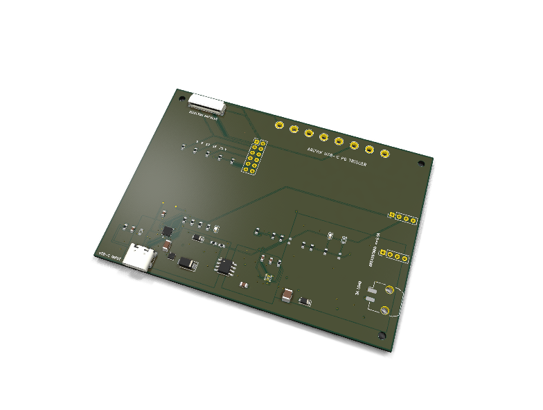
Circuit review & bench-test guide →
Components#
Every placed component, with the reason it is on the board. Extracted directly from the schematic, so this cannot drift from the design.
| Ref | Value | What it does on this board | Part number | Footprint |
|---|---|---|---|---|
C1 |
2.2uF 50V X7R | — | GRM31CR71H225KA88LMurata |
C_1206_3216Metric |
C2 |
1uF 10V X7R | — | GRM188R71A105KA61DMurata |
C_0603_1608Metric |
C3 |
330pF 50V C0G | — | GRM1885C1H331JA01DMurata |
C_0603_1608Metric |
C4 |
2.2nF 50V C0G | — | GRM1885C1H222JA01DMurata |
C_0603_1608Metric |
C5 |
1uF 50V X7R | — | GRM21BR71H105KA12LMurata |
C_0805_2012Metric |
C6 |
10uF 50V X7R | — | GRM32ER71H106KA12LMurata |
C_1210_3225Metric |
C8 |
4.7nF 50V C0G | — | GRM1885C1H472JA01DMurata |
C_0603_1608Metric |
D1 |
TVS2200 | 22 V flat-clamp VBUS surge protector | TVS2200DRVRTexas Instruments Datasheet ↗ |
WSON-6-1EP_2x2mm_P0.65mm_EP1x1.6mm |
D2 |
B340A | Negative VBUS transient clamp | B340A-13-FDiodes Incorporated Datasheet ↗ |
D_SMA |
D3 |
BZT52H-C10 | 10 V PMOS gate-source clamp | BZT52H-C10,115Nexperia Datasheet ↗ |
D_SOD-123F |
D4 |
PD FAULT RED | — | APT1608SURCKKingbright |
LED_0603_1608Metric |
D5 |
PMEG4010EH | Negative output transient clamp | PMEG4010EH,115Nexperia Datasheet ↗ |
D_SOD-123F |
D6 |
OUTPUT GREEN | — | APT1608SGCKingbright |
LED_0603_1608Metric |
D7 |
EFUSE FAULT RED DNP | — | APT1608SURCKKingbright |
LED_0603_1608Metric |
J1 |
USB4105-GF-A-120 | USB Type-C USB2.0 receptacle | USB4105-GF-A-120GCT Datasheet ↗ |
USB_C_Receptacle_GCT_USB4105-xx-A_16P_TopMnt_Horizontal |
J2 |
DP5T SELECTOR HARNESS | SMT panel-selector harness connector | SM12B-SRSS-TB(LF)(SN)JST Datasheet ↗ |
JST_SH_SM12B-SRSS-TB_1x12-1MP_P1.00mm_Horizontal |
J3 |
DP5T SELECTOR DEV DNP | Optional selector breadboard header | — | PinHeader_2x06_P2.54mm_Vertical |
J4 |
FULL LOAD SMT POWER OUT | Tape-and-reel Micro-Fit 3.0 full-load output | 43650-0210Molex Datasheet ↗ |
Molex_Micro-Fit_3.0_43650-0210_1x02-1MP_P3.00mm_Horizontal_PnP |
J5 |
BREADBOARD LIGHT LOAD <=0.5A DNP | Optional duplicated light-load header | — | PinHeader_1x04_P2.54mm_Vertical |
J6 |
STATUS / MEASURE DNP | Optional status header | — | PinHeader_1x04_P2.54mm_Vertical |
Q1 |
DMP4015SSS-13 | 40 V P-channel contract switch | DMP4015SSS-13Diodes Incorporated Datasheet ↗ |
SO-8_3.9x4.9mm_P1.27mm |
R1 |
900k 1% | — | RC0603FR-07900KLYageo Datasheet ↗ |
R_0603_1608Metric |
R2 |
900k 1% | — | RC0603FR-07900KLYageo Datasheet ↗ |
R_0603_1608Metric |
R3 |
21.0k 1% | — | RC0603FR-0721KLYageo Datasheet ↗ |
R_0603_1608Metric |
R4 |
2.2k | — | RC0603FR-072K2LYageo Datasheet ↗ |
R_0603_1608Metric |
R5 |
10k | — | RC0603FR-0710KLYageo Datasheet ↗ |
R_0603_1608Metric |
R6 |
100k | — | RC0603FR-07100KLYageo Datasheet ↗ |
R_0603_1608Metric |
R7 |
0R 1% | — | RC0603JR-070RLYageo Datasheet ↗ |
R_0603_1608Metric |
R8 |
3.00k 1% | — | RC0603FR-073KLYageo Datasheet ↗ |
R_0603_1608Metric |
R9 |
6.04k 1% | — | RC0603FR-076K04LYageo Datasheet ↗ |
R_0603_1608Metric |
R10 |
11.0k 1% | — | RC0603FR-0711KLYageo Datasheet ↗ |
R_0603_1608Metric |
R11 |
19.1k 1% | — | RC0603FR-0719K1LYageo Datasheet ↗ |
R_0603_1608Metric |
R12 |
470k 1% | — | RC0603FR-07470KLYageo Datasheet ↗ |
R_0603_1608Metric_NoSilk |
R14 |
1.74M 1% | — | RC0603FR-071M74LYageo Datasheet ↗ |
R_0603_1608Metric_NoSilk |
R15 |
100k 1% | — | RC0603FR-07100KLYageo Datasheet ↗ |
R_0603_1608Metric_NoSilk |
R16 |
47k DNP | — | RC0603FR-0747KLYageo Datasheet ↗ |
R_0603_1608Metric_NoSilk |
R17 |
976R 1% | — | RC0603FR-07976RLYageo Datasheet ↗ |
R_0603_1608Metric |
R18 |
187k 1% | — | RC0603FR-07187KLYageo Datasheet ↗ |
R_0603_1608Metric_NoSilk |
R19 |
33.0k 1% | — | RC0603FR-0733KLYageo Datasheet ↗ |
R_0603_1608Metric_NoSilk |
R20 |
4.7k | — | RC0603FR-074K7LYageo Datasheet ↗ |
R_0603_1608Metric_NoSilk |
R21 |
10k DNP | — | RC0603FR-0710KLYageo Datasheet ↗ |
R_0603_1608Metric_NoSilk |
R22 |
1M | — | RC0603FR-071MLYageo Datasheet ↗ |
R_0603_1608Metric |
R23 |
0R SHIELD LINK DNP | — | RC0603JR-070RLYageo Datasheet ↗ |
R_0603_1608Metric |
TP1 |
VBUS_RAW DNP | Electrical test point | — | TestPoint_Plated_Hole_D2.0mm |
TP2 |
PD_VBUS DNP | Electrical test point | — | TestPoint_Plated_Hole_D2.0mm |
TP3 |
VOUT DNP | Electrical test point | — | TestPoint_Plated_Hole_D2.0mm |
TP4 |
VOUT_SENSE DNP | Electrical test point | — | TestPoint_Plated_Hole_D2.0mm |
TP5 |
CC1 DNP | Low-capacitance USB-PD CC probe pad | — | CC_TestPoint_D0.6mm |
TP6 |
CC2 DNP | Low-capacitance USB-PD CC probe pad | — | CC_TestPoint_D0.6mm |
TP7 |
GND DNP | Electrical test point | — | TestPoint_Plated_Hole_D2.0mm |
TP8 |
SNK_VSET DNP | Electrical test point | — | TestPoint_Plated_Hole_D2.0mm |
TP9 |
HUSB_EN_N DNP | Electrical test point | — | TestPoint_Plated_Hole_D2.0mm |
TP10 |
PMOS_GATE DNP | Electrical test point | — | TestPoint_Plated_Hole_D2.0mm |
U1 |
HUSB238A-BB001 | Autonomous USB PD sink controller | HUSB238A-BB001Hynetek Datasheet ↗ |
QFN-16-1EP_3x3mm_P0.5mm_EP1.7x1.7mm_ThermalVias |
U2 |
TPS259470A | Reverse-blocking active-current-limit eFuse | TPS259470ARPWRTexas Instruments Datasheet ↗ |
Texas_RPW0010A_VQFN-HR-10_2x2mm_P0.45mm |
Signals#
Net labels used in the schematic, which are also the names the HDL top level should use.
CC1 CC2 DEBUG_N EFUSE_DVDT EFUSE_FLT_N EFUSE_ILM EFUSE_ITIMER EFUSE_LED_A EFUSE_OVLO EN_HVDCP EN_UVLO GND HUSB_EN_N HUSB_GATE HUSB_VDD PD_FAULT PD_FAULT_LED_A PD_VBUS PMOS_GATE SNK_ISET SNK_VSET USB_DM USB_DP USB_SHIELD VBUS_RAW VOUT VOUT_LED_A VOUT_SENSE VSET_12 VSET_15 VSET_20 VSET_5 VSET_9
Production status#
| Schematic ERC | not run |
|---|---|
| PCB layout | complete |
| DRC | not run |
| Fab package | not exported |
| Fabricated | no — design stage only |
Source: boards/usb-c-pd-trigger
Status#
Revision 0.1 is an actively generated KiCad design. It is a 60 W-class, power-only USB-C Power Delivery sink with a five-position voltage selector, contract-controlled disconnect, protected 3 A output, terminal output, and a light-load breadboard interface.
The design sources and generated artifacts all live in this folder. The routed usb-c-pd-trigger.kicad_pcb is the controlled production source. Run generate_design.py to rebuild the schematic and project libraries; generate_pcb.py creates an explicitly named unrouted placement/plane foundation for routing experiments and will not overwrite the reviewed board without --force. finalize_routing.py reapplies the reviewed footprints, qualified metadata, and plane transfers to the controlled routed PCB.
Run the complete release gate with:
python3 boards/usb-c-pd-trigger/qa/run_release_qa.py --refresh --strict
python3 boards/usb-c-pd-trigger/qa/validate_report.py
The generated HTML QA report is the release index for CAD, analysis, simulation, manufacturing, bench, and certification evidence.
Electrical architecture#
USB-C receptacle
  |-- CC1/CC2, D+/D- --> HUSB238A-BB001 autonomous PD sink
  |                         |-- SNK_VSET <- fail-safe 2-pole selector
  |                         |-- SNK_ISET = 21.0 kOhm (3 A request)
  |                         `-- GATE --> 40 V P-MOSFET contract switch
  |
  `-- VBUS_RAW --> TVS2200 --> contract PMOS --> TPS259470A eFuse --> VOUT
                                                         |        |-- terminal
                                                         |        `-- light-load header
                                                         `-- current limit, inrush,
                                                             UVLO/OVLO, reverse block
HUSB238A-BB001 is frozen because Hynetek identifies it as the no-SOP-prime orderable variant. The board only uses conventional SPR fixed PDOs up to 20 V. PPS, AVS, EPR, and 5 A operation are intentionally out of scope.
Fail-safe selector#
A simple one-pole rotary is not acceptable here: HUSB238A interprets an open SNK_VSET as its highest voltage code. Revision 0.1 therefore uses a break-before-make 2-pole, 5-position selector:
- pole A selects one of the five precision
SNK_VSETresistors; - pole B connects
EN_Nto ground at every valid detent; - between detents, pole B opens, the controller's internal pull-up disables the controller, and
GATEturns the external P-MOSFET off; - after the switch reaches a detent, the controller reinitializes and samples the now-stable resistor before reconnecting the output.
| Position | SNK_VSET | Preferred voltage ceiling |
|---|---|---|
| 1 | 0 Ohm | 5 V |
| 2 | 3.00 kOhm, 1% | 9 V |
| 3 | 6.04 kOhm, 1% | 12 V |
| 4 | 11.0 kOhm, 1% | 15 V |
| 5 | 19.1 kOhm, 1% | 20 V |
SNK_ISET uses 21.0 kOhm, 1%, for a preferred 3 A request. The knob is a ceiling, not a voltmeter: HUSB238A searches downward for the highest source PDO that does not exceed the selected voltage and can supply the requested current. If no source PDO meets both requirements, it reports a capability mismatch. Always measure VOUT before connecting a voltage-sensitive load.
Selector interfaces#
J2is the production SMT harness connector (JSTSM12B-SRSS-TB). The frozen panel switch is Grayhill56A36-01-2-05N, whose manufacturer listing explicitly specifies two poles, five positions, and non-shorting contacts. Any alternate must have documented break-before-make contacts and must pass the harness continuity/interlock test in the QA report.J3is an optional 2x6, 2.54 mm development header carrying the same nets. It is DNP in the core SMT build and is intended for a breadboard selector or continuity testing.
The panel switch/harness is a mechanical subassembly rather than a reflowed component. This keeps the core PCB compatible with automated SMT assembly and lets the rotary control mount to an enclosure without stressing the PCB.
Protection and operating limits#
- Input target: USB PD SPR, 5 V through 20 V, 3 A maximum.
TVS2200DRVR: 22 V standoff flat-clamp protection at the USB-C input.DMP4015SSS-13: 40 V P-channel contract switch driven by HUSB238AGATE, with a 10 V gate clamp.TPS259470ARPWR: true reverse-current blocking eFuse with controlled output slew, active current limiting, short-circuit fast trip, thermal shutdown, UVLO, OVLO, and fault indication.- The 976 Ohm
ILMresistor is chosen so the low tolerance corner remains approximately 3 A; the nominal current limit is intentionally above 3 A to avoid nuisance limiting. - A 470 kOhm pull-up enables the eFuse as documented by TI for input rails above 5 V; the lower divider leg is intentionally omitted, so the internal 2.44-2.64 V input UV protection is used without overdriving the 6.5 V-rated
EN/UVLOpin. The OVLO divider is designed to pass a 20 V PDO at its allowed high corner while cutting off before prolonged operation above the eFuse's recommended 23 V input limit. - The high-current path targets 3 A. The 2.54 mm breadboard output is explicitly limited to 0.5 A; use the Micro-Fit
J4harness for load and thermal testing. Do not route 3 A through a solderless breadboard. D2is the exact SMAB340A-13-F40 V / 3 A negative-input clamp.D5is the exact SOD123FPMEG4010EH,11540 V / 1 A negative-output clamp. These orderable/package pairs replace the mismatched provisional review values.- The module is SELV-side only. It provides no mains isolation and is not a certified power supply.
Outputs and measurements#
J4: tape-and-reel Molex43650-0210Micro-Fit 3.0 full-load output (VOUT,GND). Use mating housing43645-0200, appropriate female crimp contacts, and 18-20 AWG wire for the 3 A test harness.J5: duplicated 2.54 mm light-load output (VOUT,VOUT,GND,GND).J6: status/measurement header (VOUT_SENSE,PD_FAULT,EFUSE_FLT_N,GND).EFUSE_FLT_Nis an open-drain debug output: use an external pull-up to 5 V or less.R16,R21, andD7are mandatory DNP because the eFuse FLT pin is only 5 V recommended / 6.5 V absolute maximum; the protected output can be 20 V.- Test points: raw VBUS, contract-switched VBUS, protected output, divided output sense, CC1, CC2, ground, selector voltage, enable, and PMOS gate.
- The
VOUT_SENSEdivider is 187 kOhm / 33 kOhm. It produces 3.00 V at 20 V nominal and remains below 3.21 V at 21 V with 1% resistor tolerance. The receiving ADC must still be rated for at least 3.3 V and share board GND. - The green LED means only that protected output voltage is present. It does not prove that the knob voltage or 3 A capability was obtained.
Assembly variants#
CORE_SMT: populate all SMT electronics, selector connectorJ2, and the full-load Micro-Fit outputJ4; DNP the breadboard/debug headers and test points.R16,R21, andD7are also mandatory DNP to keep high voltage away fromEFUSE_FLT_N. Both production connectors are supplied in tape-and-reel packaging.MIXED_PROTOTYPE: addJ3,J5,J6, and the plated test points. The pin headers require a mixed-technology or hand-finish assembly operation.- The external DP5T rotary switch and harness are always a separate mechanical assembly.
Release status#
The automated QA report distinguishes CAD/analysis evidence from physical evidence. The current rev-0.1 release has 41 PASS, 5 CONDITIONAL, 18 OPEN, and 0 FAIL results. Passing ERC, DRC, corner calculations, simulations, BOM/PnP parity, and fabrication-file checks does not constitute USB-IF, FCC, CE, UL, or other certification. Hardware remains prototype-only until every required bench and certification item in the HTML report is closed.
Primary references#
- Hynetek HUSB238A product page and Rev. 0.1 full data sheet; the current product page identifies
HUSB238A-BB001andHUSB238A-BB002. - Texas Instruments TPS25947 Rev. C data sheet.
- Texas Instruments TVS2200 Rev. C data sheet.
- Diodes Incorporated DMP4015SSS data sheet.
- GCT USB4105 product page and B4 mechanical drawing.
- Grayhill Series 56 selector data and
56A36-01-2-05Nproduct record. - Molex
43650-0210Micro-Fit 3.0 product record and drawing. - USB Type-C and USB Power Delivery specifications; formal compliance testing requires access to the licensed specifications and an authorized test setup.