Actuator modules
AXA-012 — E-stop / power gate PMOD module
Catalog #12 in the AruviX actuator line, level L2. High-side P-FET power gate with a normally-closed e-stop loop and a host enable, ANDed in discrete logic.
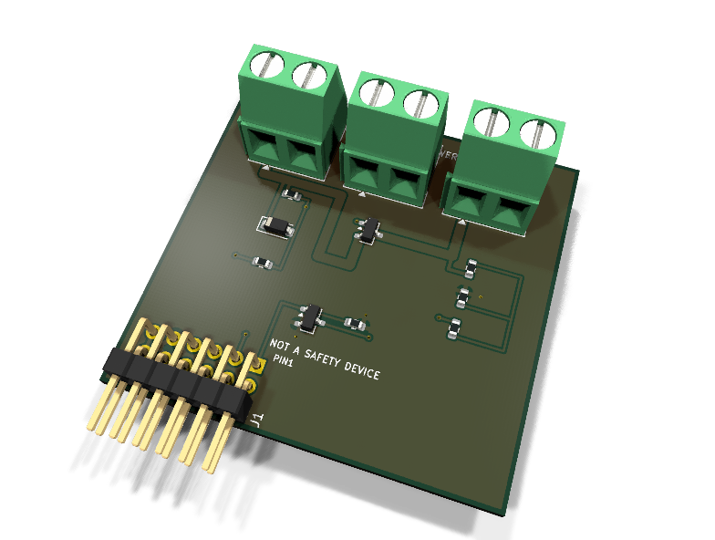
Circuit review & bench-test guide →
Components#
Every placed component, with the reason it is on the board. Extracted directly from the schematic, so this cannot drift from the design.
| Ref | Value | What it does on this board | Part number | Footprint |
|---|---|---|---|---|
D1 |
10V zener | Gate-source zener clamp: Vsg <= 10 V at any VIN in range | not selected Diodes Inc. Datasheet ↗ |
D_SOD-123 |
J1 |
PMOD PLUG 2x6 | PMOD peripheral plug (Digilent spec 1.2) | not selected generic |
PinHeader_2x06_P2.54mm_Horizontal |
J2 |
VIN 5-24V | Gated supply input: 1 VIN (5-24 V), 2 GND (joins PMOD GND here) | not selected Phoenix Contact |
TerminalBlock_Phoenix_MKDS-1,5-2-5.08_1x02_P5.08mm_Horizontal |
J3 |
VOUT (GATED) | Gated supply output: 1 VOUT, 2 GND | not selected Phoenix Contact |
TerminalBlock_Phoenix_MKDS-1,5-2-5.08_1x02_P5.08mm_Horizontal |
J4 |
E-STOP LOOP (NC) | Normally-closed e-stop loop: wire a NC mushroom button (or a wire link) across 1-2; opening the loop kills VOUT | not selected Phoenix Contact |
TerminalBlock_Phoenix_MKDS-1,5-2-5.08_1x02_P5.08mm_Horizontal |
Q1 |
AO3401A | P-channel MOSFET -30 V -4 A, SOT-23, high-side power switch | AO3401AAlpha & Omega Datasheet ↗ |
SOT-23 |
Q2 |
2N7002 | N-channel MOSFET 60 V 115 mA, SOT-23, EN gate switch | 2N7002LT1Gonsemi Datasheet ↗ |
SOT-23 |
R1 |
10k | Gate pull-up: P-FET OFF unless the pull-down chain conducts | RC0603FR-0710KLYageo Datasheet ↗ |
R_0603_1608Metric |
R2 |
10k | Gate series/divider resistor: with R1 sets Vsg = VIN/2 before the zener clamp | RC0603FR-0710KLYageo Datasheet ↗ |
R_0603_1608Metric |
R3 |
10k | EN pull-down: unpowered/unconfigured host = OUTPUT OFF | RC0603FR-0710KLYageo Datasheet ↗ |
R_0603_1608Metric |
R4 |
100k | STATUS divider top (sized for 24 V; repopulate for lower VIN - see README) | RC0603FR-07100KLYageo Datasheet ↗ |
R_0603_1608Metric |
R5 |
10k | STATUS divider bottom: 24 V -> 2.18 V at the tap | RC0603FR-0710KLYageo Datasheet ↗ |
R_0603_1608Metric |
R6 |
100R | Series protection on the module-driven STATUS line | RC0603FR-07100RLYageo Datasheet ↗ |
R_0603_1608Metric |
Signals#
Net labels used in the schematic, which are also the names the HDL top level should use.
3V3 EN GND LOOP_A LOOP_B PGATE STATUS ST_DIV VIN VOUT
Production status#
| Schematic ERC | 0 violations |
|---|---|
| PCB layout | complete |
| DRC | 0 violations |
| Fab package | exported (24 gerbers + drill + CPL + BOM) |
| Fabricated | no — design stage only |
Source: boards/actuator-modules/axa-012-estop
Catalog #12 in the AruviX actuator line (../README.md), level L2. High-side P-FET power gate with a normally-closed e-stop loop and a host enable, ANDed in discrete logic.
Status: schematic generated, ERC clean (0/0), netlist reviewed. PCB layout not started. Not released.
NOT A CERTIFIED SAFETY DEVICE. This is a safety-themed lesson: no redundancy, no monitored contacts, no rated stop category, single transistor in the power path. Never make a person's safety depend on it. Real machines use rated safety relays and follow ISO 13849 / IEC 62061.
What it teaches#
Fail-safe thinking in discrete hardware plus the fabric's role in a safety chain: series NC loops (a cut wire is a stop, not a fault you miss), default-off pull-downs, gate-voltage clamping across a wide rail range, and why the latching part of an e-stop belongs in supervised logic.
How the gate works#
Q1 (AO3401A P-FET) passes VIN→VOUT only when its gate is pulled below the rail. The only pull-down path is a series chain:
PGATE → R2 (10k) → J4 e-stop loop (normally closed) → Q2 (2N7002) → GND
with R1 (10 k) pulling PGATE up to VIN (default OFF) and D1 (10 V zener, VIN→PGATE) clamping V_SG.
| J4 loop | EN (PMOD 1) | Q2 | Pull-down path | VOUT |
|---|---|---|---|---|
| closed | high | on | conducts | ON |
| closed | low / host unpowered (R3 10k pull-down) | off | broken | OFF |
| open (button hit / wire cut) | any | any | broken | OFF |
Gate voltage: R1/R2 form a 1:1 divider, so V_SG = VIN/2 (2.5 V at VIN = 5 V — enough for the AO3401A, which is specified at V_GS = −2.5 V); at 24 V the divider would give 12 V, exactly the ±12 V gate abs-max, so D1 clamps V_SG to 10 V. Usable VIN: 5–24 V.
No auto-relatch is a fabric contract, not a hardware feature. The hardware AND is combinational: if the loop recloses while EN is still high, power returns. Your HDL must latch any STATUS drop and require a deliberate EN toggle (off → on) before re-asserting. That supervision FSM is the exercise; the README-level truth table above is what the testbench must prove, plus the latch.
Design notes#
- Q1 = AO3401A (SOT-23, −30 V / −4 A abs max). Stock KiCad has no larger SO-8 P-FET (AO4407 class absent; IRF9540N is TO-220 through-hole), so the SOT-23 part is used and derated: ≤ 2 A continuous, ≤ 24 V — fine for small-robot rails. R_DS(on) ≈ 60 mΩ → ~0.24 W at 2 A: watch it thermally.
- STATUS: VOUT through a 100k/10k divider (tap = VOUT/11, 2.18 V at 24 V) then 100 Ω series to PMOD 2 (line rule). The divider is sized for 24 V systems; on lower rails the tap never reaches V_IH, so repopulate R4: 24 V → 100k (fitted), 12 V → 39k, 5 V → 10k (tap ≈ 2.5 V). The tap can never exceed 3.3 V-safe levels with the fitted values.
- E-stop input J4: wire a normally-closed mushroom button (or chain of NC contacts) across the 1x02 terminal. Unused position = fit a wire link.
- All terminals are MKDS 1x02 screw terminals; grounds join on the module.
- No decoupling caps: there is no IC and the gate net must not be slowed artificially (the P-FET turn-off through R1 is the stop path).
| PMOD pin | 1 | 2 | 3 | 4 | 5 | 6 | 7 | 8 | 9 | 10 | 11 | 12 |
|---|---|---|---|---|---|---|---|---|---|---|---|---|
| Net | EN | STATUS | NC | NC | GND | 3V3 | NC | NC | NC | NC | GND | 3V3 |
Regenerate#
python3 generate_design.pyRemaining for release#
- [ ] PCB layout (20 × 40 mm actuator outline, wide VIN/VOUT copper), DRC, fab outputs
- [ ]
hdl/: e-stop supervisor FSM (latch, EN-toggle relatch, STATUS debounce), self-checking testbench, ECP5 demo - [ ] BOM export and availability check (pin the zener MPN), design-review checklist