Comms modules
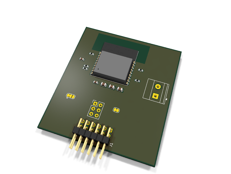
AXC-003 — ESP32-C3 WiFi/BLE co-processor PMOD module
Catalog #3 in the AruviX comms line, level L3 (UART AT modem). The FPGA stays the brain; the ESP32-C3 is a modem speaking the Espressif AT command set. The platform's path to MQTT/cloud demos.
Circuit review & bench-test guide →
Components#
Every placed component, with the reason it is on the board. Extracted directly from the schematic, so this cannot drift from the design.
| Ref | Value | What it does on this board | Part number | Footprint |
|---|---|---|---|---|
C1 |
1uF 10V X7R | EN power-on delay / glitch filter | GRM188R71A105KA61DMurata |
C_0603_1608Metric |
C2 |
100nF 16V X7R | Module HF decoupling | GRM188R71C104KA01DMurata |
C_0603_1608Metric |
C3 |
10uF 10V X5R | WiFi TX burst bulk reservoir (~350 mA bursts, line current-spike rule) | GRM21BR61A106KE19LMurata |
C_0805_2012Metric |
C4 |
10uF 10V X5R | WiFi TX burst bulk reservoir (~350 mA bursts, line current-spike rule) | GRM21BR61A106KE19LMurata |
C_0805_2012Metric |
C5 |
10uF 10V X5R | WiFi TX burst bulk reservoir (~350 mA bursts, line current-spike rule) | GRM21BR61A106KE19LMurata |
C_0805_2012Metric |
J1 |
PMOD PLUG 2x6 | PMOD peripheral plug (Digilent spec 1.2) | not selected generic |
PinHeader_2x06_P2.54mm_Horizontal |
J2 |
ESP SPI (DNP) DNP | esp-hosted SPI upgrade header: IO6/IO7/IO2/IO10 + IO3/IO4 handshake; roles are firmware-defined | not selected generic |
PinHeader_2x03_P2.54mm_Vertical |
J3 |
EXT 3V3 IN (DNP) DNP | External 3.3 V feed: 1 +3V3, 2 GND (common with PMOD GND). Fit for JP2 2-3. | not selected Phoenix Contact |
TerminalBlock_Phoenix_MKDS-1,5-2-5.08_1x02_P5.08mm_Horizontal |
JP1 |
EN FROM HOST | Bridged (default): PMOD pin 1 controls ESP EN. Cut to hand EN to R1 only. | — | SolderJumper-2_P1.3mm_Bridged_RoundedPad1.0x1.5mm |
JP2 |
PWR: PMOD/EXT | ESP rail source: 1-2 (default) PMOD 3V3; 2-3 external 3.3 V from J3 | — | SolderJumper-3_P1.3mm_Bridged12_RoundedPad1.0x1.5mm |
R1 |
10k | EN pull-up: module runs with JP1 cut or host pin floating | RC0603FR-0710KLYageo Datasheet ↗ |
R_0603_1608Metric |
R2 |
10k | GPIO9/BOOT pull-up: normal SPI boot; host drives low for download mode | RC0603FR-0710KLYageo Datasheet ↗ |
R_0603_1608Metric |
R3 |
10k | GPIO2 strap pull-up (must be 1 for both boot modes) | RC0603FR-0710KLYageo Datasheet ↗ |
R_0603_1608Metric |
R4 |
10k | GPIO8 strap pull-up (must be 1 for download mode) | RC0603FR-0710KLYageo Datasheet ↗ |
R_0603_1608Metric |
R5 |
100R | Series protection on the module-driven UART TX line | RC0603FR-07100RLYageo Datasheet ↗ |
R_0603_1608Metric |
U1 |
ESP32-C3-WROOM-02 | WiFi 4 + BLE 5 module, ESP32-C3, 4 MB flash, PCB antenna | ESP32-C3-WROOM-02-N4Espressif Datasheet ↗ |
ESP32-C3-WROOM-02 |
Signals#
Net labels used in the schematic, which are also the names the HDL top level should use.
3V3 BOOT EN EN_HOST ESP_3V3 ESP_IO10 ESP_IO2 ESP_IO3 ESP_IO4 ESP_IO6 ESP_IO7 ESP_IO8 ESP_TX EXT_3V3 GND RXD TXD
Production status#
| Schematic ERC | 0 violations |
|---|---|
| PCB layout | complete |
| DRC | not run |
| Fab package | not exported |
| Fabricated | no — design stage only |
Source: boards/comms-modules/axc-003-wifi
Catalog #3 in the AruviX comms line (../README.md), level L3 (UART AT modem). The FPGA stays the brain; the ESP32-C3 is a modem speaking the Espressif AT command set. The platform's path to MQTT/cloud demos.
Part substitution (per line README): the catalog's ESP32-C3-MINI-1 has no stock KiCad symbol; this module uses the ESP32-C3-WROOM-02 (stock symbol + footprint, same C3 silicon, mature AT firmware).
Status: schematic generated, ERC clean (0/0), netlist reviewed. PCB layout not started. Not released.
What it teaches#
UART with a command/response modem protocol, AT-set flow parsing in fabric or AruviOS, WiFi/BLE provisioning, MQTT publish pipelines — and a firmware upgrade path: reflash with esp-hosted and move to SPI on the DNP J2 header (README open decision resolved: yes, the SPI pins are routed, header DNP).
Design#
- PMOD Type 3: pin 1 carries ESP EN through solder jumper JP1 (bridged by default = host controls reset; cut to isolate), pin 2 TXD → ESP RX (IO20), pin 3 RXD ← ESP TX (IO21) via 100 Ω, pin 4 = GPIO9/BOOT with 10 k pull-up — host drives it low + pulses EN for ROM download mode.
- Strap pull-ups (10 k): GPIO9 (BOOT), GPIO2 and GPIO8 (must be 1 for the boot modes); EN has 10 k + 1 µF delay/glitch cap.
- J2 (2×03, DNP) routes IO6/IO7/IO2/IO10 + IO3/IO4 for esp-hosted SPI + handshake/data-ready; pin roles are firmware-defined — confirm against the esp-hosted docs at bring-up.
- Power (line current-spike rule): WiFi TX bursts ≈ 350 mA vs the ~100 mA PMOD guidance (
pmod-common/PMOD-SPEC-NOTES.md). The module stays 3V3-only by default with strong local bulk (3 × 10 µF 0805 + 100 nF). JP2 selects the rail source: 1-2 (default) PMOD 3V3, 2-3 external 3.3 V on the DNP screw terminal J3 — cutting the 1-2 side fully isolates the PMOD 3V3 pin. Verify the host budget before long TX sessions. - RF keep-out: PCB antenna end of the WROOM faces away from the PMOD plug, no copper under it (line rule).
| PMOD pin | 1 | 2 | 3 | 4 | 5 | 6 | 7–10 | 11 | 12 |
|---|---|---|---|---|---|---|---|---|---|
| Net | EN (JP1) | TXD | RXD | GPIO9/BOOT | GND | 3V3 | NC | GND | 3V3 |
Regenerate#
python3 generate_design.pyRemaining for release#
- [ ] PCB layout (antenna overhang/keep-out, bulk caps at the module pins), DRC, fab outputs
- [ ] Host 3.3 V budget measurement on the ECP5 rev-A PMOD rail
- [ ]
hdl/: UART + AT-parser demo, AruviOS MQTT lesson - [ ] BOM export and availability check, design-review checklist