Actuator modules
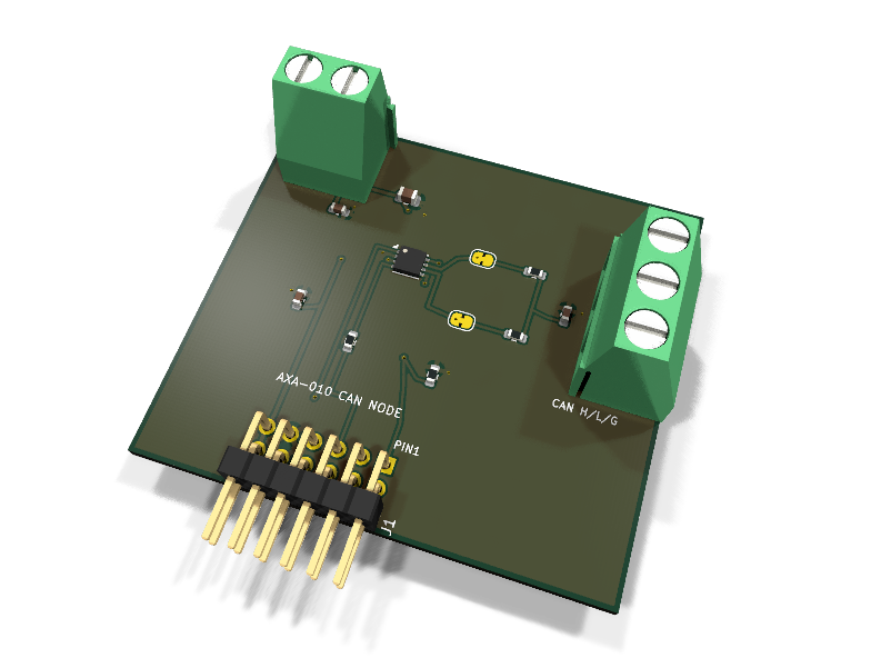
AXA-010 — CAN bus node PMOD module
Catalog #10 in the AruviX actuator line, level L4. Microchip MCP2542WFD CAN FD transceiver — deliberately only a transceiver. No MCP2515, no controller silicon.
Circuit review & bench-test guide →
Components#
Every placed component, with the reason it is on the board. Extracted directly from the schematic, so this cannot drift from the design.
| Ref | Value | What it does on this board | Part number | Footprint |
|---|---|---|---|---|
C1 |
4.7nF 50V X7R | Split-termination common-mode filter capacitor | GRM188R71H472KA01DMurata |
C_0603_1608Metric |
C2 |
100nF 16V X7R | VDD decoupling | GRM188R71C104KA01DMurata |
C_0603_1608Metric |
C3 |
100nF 16V X7R | VIO decoupling | GRM188R71C104KA01DMurata |
C_0603_1608Metric |
C4 |
10uF 25V X5R | VDD bulk reservoir | GRM21BR61E106KA73LMurata |
C_0805_2012Metric |
J1 |
PMOD PLUG 2x6 | PMOD peripheral plug (Digilent spec 1.2) | not selected generic |
PinHeader_2x06_P2.54mm_Horizontal |
J2 |
5V IN (VDD) | Transceiver supply input: 1 V5_CAN (4.5-5.5 V), 2 GND (joins PMOD GND here) | not selected Phoenix Contact |
TerminalBlock_Phoenix_MKDS-1,5-2-5.08_1x02_P5.08mm_Horizontal |
J3 |
CAN BUS (H/L/GND) | CAN bus: 1 CANH, 2 CANL, 3 GND reference | not selected Phoenix Contact |
TerminalBlock_Phoenix_MKDS-1,5-3-5.08_1x03_P5.08mm_Horizontal |
JP1 |
TERM H | Termination enable, CANH leg (bridged = terminated) | — | SolderJumper-2_P1.3mm_Bridged_RoundedPad1.0x1.5mm |
JP2 |
TERM L | Termination enable, CANL leg (bridged = terminated) | — | SolderJumper-2_P1.3mm_Bridged_RoundedPad1.0x1.5mm |
R1 |
100R | Series protection on the transceiver-driven RXD line | RC0603FR-07100RLYageo Datasheet ↗ |
R_0603_1608Metric |
R2 |
10k | STBY pull-down: normal mode by default (STBY high = standby) | RC0603FR-0710KLYageo Datasheet ↗ |
R_0603_1608Metric |
R3 |
60.4R 1% | Split termination, CANH half (2x60.4R = 120R differential) | RC0603FR-0760R4LYageo Datasheet ↗ |
R_0603_1608Metric |
R4 |
60.4R 1% | Split termination, CANL half | RC0603FR-0760R4LYageo Datasheet ↗ |
R_0603_1608Metric |
U1 |
MCP2542WFD | CAN FD transceiver, 8 Mbps, VIO for 3.3 V logic, wake-on-CAN standby | MCP2542WFD-E/MFMicrochip Datasheet ↗ |
DFN-8-1EP_3x3mm_P0.65mm_EP1.55x2.4mm |
Signals#
Net labels used in the schematic, which are also the names the HDL top level should use.
3V3 CANH CANH_T CANL CANL_T CAN_RXD GND RXD STBY TSPLIT TXD V5_CAN
Production status#
| Schematic ERC | 0 violations |
|---|---|
| PCB layout | complete |
| DRC | 0 violations |
| Fab package | exported (24 gerbers + drill + CPL + BOM) |
| Fabricated | no — design stage only |
Source: boards/actuator-modules/axa-010-can
Catalog #10 in the AruviX actuator line (../README.md), level L4. Microchip MCP2542WFD CAN FD transceiver — deliberately only a transceiver. No MCP2515, no controller silicon.
Status: schematic generated, ERC clean (0/0), netlist reviewed. PCB layout not started. Not released.
What it teaches#
The CAN controller lives in fabric — that is the lesson. Bit stuffing, CRC-15, arbitration (dominant/recessive, lose-and-retry), ACK slots and error frames are all implemented in the can_ctrl HDL core; the MCP2542WFD only converts TXD/RXD to the differential pair. When two nodes arbitrate on a scope, you see your own state machine win or yield.
Design#
- MCP2542WFD-E/MF (Microchip, DFN-8 3×3 mm). CAN FD up to 8 Mbps, wake-on-CAN standby.
- The stock library only carries the DFN (xMF) symbol/footprint pair, so the /MF package is used rather than the SOIC /SN named in the catalog sketch — same die, same pinout function.
- Supply split per the line rule: VDD needs 4.5–5.5 V, so it enters on the J2 screw terminal (net
V5_CAN, PWR_FLAGged). VIO ties the logic interface to the PMOD 3.3 V — RXD/TXD swing 3.3 V, no level shifting. - STBY polarity (checked against the datasheet): HIGH = standby. R2 10 k pull-down keeps the node in normal mode by default; the host drives PMOD 1 high to enter wake-on-bus standby.
- RXD is transceiver-driven and passes R1 100 Ω (line rule).
- Bus terminal J3: 1x03 screw terminal CANH / CANL / GND.
- Split termination: 2× 60.4 Ω 1% in series (120 Ω differential) with 4.7 nF from the midpoint to GND (common-mode filter). Each leg sits behind a solder jumper (JP1/JP2), bridged by default = terminated. Cut both to make a stub node: only the two physical ends of a CAN bus terminate; a terminated mid-bus stub ruins the bit-level waveforms — scope it and see.
| PMOD pin | 1 | 2 | 3 | 4 | 5 | 6 | 7 | 8 | 9 | 10 | 11 | 12 |
|---|---|---|---|---|---|---|---|---|---|---|---|---|
| Net | STBY | TXD | RXD | NC | GND | 3V3 | NC | NC | NC | NC | GND | 3V3 |
Regenerate#
python3 generate_design.pyRemaining for release#
- [ ] PCB layout (20 × 40 mm actuator outline, keep H/L pair short and symmetric), DRC, fab outputs
- [ ]
hdl/:can_ctrlcore (Phase C of the shared HDL library), self-checking testbench, two-node ECP5 demo - [ ] BOM export and availability check, design-review checklist