I/O modules
AXO-017 — microSD card PMOD module
Catalog #17 in the AruviX output line, level L4 (SPI-mode SD, FAT, block driver). The storage keystone of the standalone-computer path.
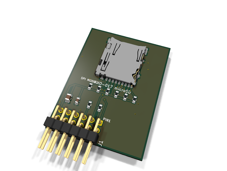
Circuit review & bench-test guide →
Components#
Every placed component, with the reason it is on the board. Extracted directly from the schematic, so this cannot drift from the design.
| Ref | Value | What it does on this board | Part number | Footprint |
|---|---|---|---|---|
C1 |
100nF 16V X7R | Card VDD high-frequency decoupling at the socket | GRM188R71C104KA01DMurata |
C_0603_1608Metric |
C2 |
10uF 10V X5R | Bulk reservoir for card write-burst current (cards pulse tens of mA) | GRM21BR61A106KE19LMurata |
C_0805_2012Metric |
J1 |
PMOD PLUG 2x6 | PMOD peripheral plug (Digilent spec 1.2) | not selected generic |
PinHeader_2x06_P2.54mm_Horizontal |
J2 |
microSD DM3AT | Hirose DM3AT-SF-PEJM5 push-push microSD socket with detect switch | DM3AT-SF-PEJM5Hirose Datasheet ↗ |
microSD_HC_Hirose_DM3AT-SF-PEJM5 |
R1 |
10k | CMD pull-up (SD spec) | RC0603FR-0710KLYageo Datasheet ↗ |
R_0603_1608Metric |
R2 |
10k | DAT3/~CS pull-up (SD spec; also keeps the card deselected before FPGA config) | RC0603FR-0710KLYageo Datasheet ↗ |
R_0603_1608Metric |
R3 |
10k | DAT0/MISO pull-up (SD spec) | RC0603FR-0710KLYageo Datasheet ↗ |
R_0603_1608Metric |
R4 |
10k | DAT1 pull-up: unused in SPI mode but must idle high | RC0603FR-0710KLYageo Datasheet ↗ |
R_0603_1608Metric |
R5 |
10k | DAT2 pull-up: unused in SPI mode but must idle high | RC0603FR-0710KLYageo Datasheet ↗ |
R_0603_1608Metric |
R6 |
10k | Card-detect pull-up: switch to GND closes on insertion, so CD reads LOW = card present | RC0603FR-0710KLYageo Datasheet ↗ |
R_0603_1608Metric |
R7 |
100R | Series protection on the card-driven MISO line | RC0603FR-07100RLYageo Datasheet ↗ |
R_0603_1608Metric |
R8 |
100R | Series protection on the module-driven card-detect line | RC0603FR-07100RLYageo Datasheet ↗ |
R_0603_1608Metric |
Signals#
Net labels used in the schematic, which are also the names the HDL top level should use.
3V3 CD CS_N GND MISO MOSI SCK SD_CD SD_DAT0 SD_DAT1 SD_DAT2
Production status#
| Schematic ERC | 0 violations |
|---|---|
| PCB layout | complete |
| DRC | 0 violations |
| Fab package | exported (24 gerbers + drill + CPL + BOM) |
| Fabricated | no — design stage only |
Source: boards/io-modules/axo-017-microsd
Catalog #17 in the AruviX output line (../README.md), level L4 (SPI-mode SD, FAT, block driver). The storage keystone of the standalone-computer path.
Status: schematic generated, ERC clean (0/0), netlist reviewed. PCB layout not started. Not released.
What it teaches#
The full storage stack, bottom-up:
- SPI-mode init sequence — power up, ≥ 74 clocks with ~CS high at 100–400 kHz, CMD0 (idle) → CMD8 (voltage check, distinguishes SDv2) → ACMD41 loop until ready → CMD58 (OCR/CCS: SDSC vs SDHC addressing), then raise the clock (≤ 25 MHz) and read 512-byte blocks with CMD17.
- FAT lesson — MBR partition table, FAT16/32 boot sector, cluster chains, root directory; first in HDL with the
sd_spi+fat_readercores, reading a file by name with no CPU at all. - AruviOS block driver — the same board then backs the OS: block device interface, filesystem mount, and finally loading programs from card on the CPU-you-wrote.
Design#
- Hirose DM3AT-SF-PEJM5 push-push socket (stock symbol
Connector:Micro_SD_Card_Det_Hirose_DM3AT, stock footprintConnector_Card:microSD_HC_Hirose_DM3AT-SF-PEJM5; pin table verified from the parentMicro_SD_Card_Det2symbol). - All SD bus lines carry the SD-spec 10 k pull-up to 3V3: CMD (R1), DAT3/~CS (R2 — also keeps the card deselected before FPGA config), DAT0 (R3), DAT1 (R4), DAT2 (R5).
- DAT1/DAT2 are required to idle high in SPI mode (a floating level during init can confuse the card's mode detection); they terminate in their pull-ups and are deliberately not broken out — the catalog's open decision is resolved as SPI-only, revisit on a rev if a 4-bit high-speed lesson is ever wanted.
- Card-detect: the DM3AT switch (DET_A/DET_B) closes to GND on insertion; 10 k pull-up (R6) + 100 R series (R8) drive PMOD pin 7 — low = card present (net
SD_CDon the module,CDat the plug). - Card-driven MISO passes 100 R (R7) per the line rule; SHIELD tied to GND; 100 nF + 10 µF at the socket for write-burst current.
- 3.3 V is the native SD interface voltage — no level shifting anywhere.
| PMOD pin | 1 | 2 | 3 | 4 | 5 | 6 | 7 | 8 | 9 | 10 | 11 | 12 |
|---|---|---|---|---|---|---|---|---|---|---|---|---|
| Net | ~CS (DAT3) | MOSI (CMD) | MISO (DAT0) | SCK (CLK) | GND | 3V3 | CD (low = card) | NC | NC | NC | GND | 3V3 |
Type 2A expanded SPI, card detect in the pin-7 interrupt slot.
Regenerate#
python3 generate_design.pyRemaining for release#
- [ ] PCB layout (socket on the far edge, card overhang, keepout under the card), DRC, fab outputs
- [ ]
hdl/: sd_spi core (init FSM + block read/write), fat_reader; AruviOS block driver - [ ] BOM export and availability check, design-review checklist