Lab modules
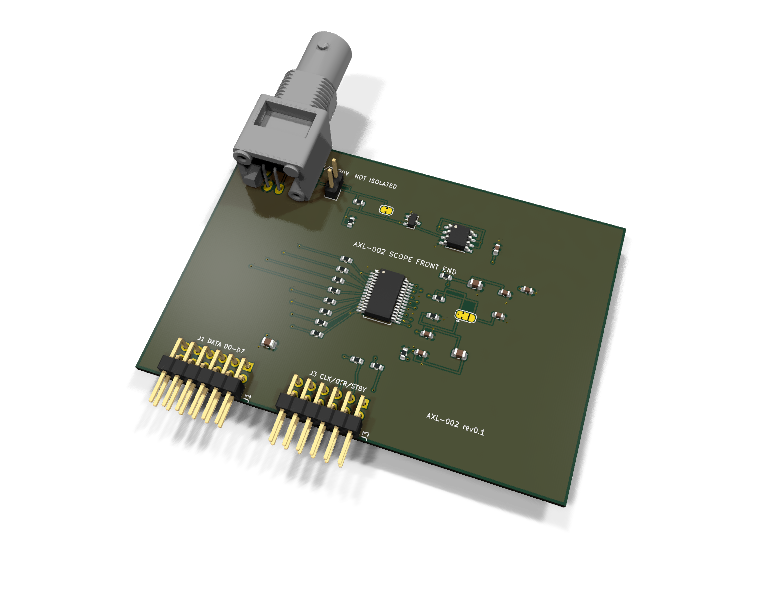
AXL-002 — Oscilloscope front end dual-PMOD module (AD9280)
Catalog #2 in the AruviX lab line, level L5 (instrument). Dual-PMOD module (binding review finding): 8 data bits + the ADC clock exceed one socket's 8 IO — same host constraint as axs-050/axo-007, plugs on 0.9" centers, and CLK needs the clock-capable host pin tracked.
Circuit review & bench-test guide →
Components#
Every placed component, with the reason it is on the board. Extracted directly from the schematic, so this cannot drift from the design.
| Ref | Value | What it does on this board | Part number | Footprint |
|---|---|---|---|---|
C3 |
100nF 16V X7R | REFTF decoupling (datasheet reference decoupling) | GRM188R71C104KA01DMurata |
C_0603_1608Metric |
C4 |
100nF 16V X7R | REFBF decoupling | GRM188R71C104KA01DMurata |
C_0603_1608Metric |
C5 |
10uF 10V X5R | Reference force-node bulk (datasheet: 10uF across REFTF-REFBF) | GRM21BR61A106KE19LMurata |
C_0805_2012Metric |
C6 |
100nF 16V X7R | VREF decoupling | GRM188R71C104KA01DMurata |
C_0603_1608Metric |
C7 |
10uF 10V X5R | AVDD filter bulk (10R + 10uF) | GRM21BR61A106KE19LMurata |
C_0805_2012Metric |
C8 |
100nF 16V X7R | AVDD decoupling at the pin | GRM188R71C104KA01DMurata |
C_0603_1608Metric |
C9 |
100nF 16V X7R | DRVDD decoupling | GRM188R71C104KA01DMurata |
C_0603_1608Metric |
C10 |
100nF 16V X7R | U2 op-amp decoupling | GRM188R71C104KA01DMurata |
C_0603_1608Metric |
C11 |
10uF 10V X5R | Module bulk decoupling at the PMOD plugs | GRM21BR61A106KE19LMurata |
C_0805_2012Metric |
D1 |
BAT54S | Input clamp: VIN held between GND-0.3V and 3V3+0.3V ahead of the buffer | BAT54S,215Nexperia Datasheet ↗ |
SOT-23 |
J1 |
PMOD A: DATA | PMOD peripheral plug (Digilent spec 1.2) | not selected generic |
PinHeader_2x06_P2.54mm_Horizontal |
J2 |
SIG IN (0-2V / 0-20V) | Signal input header: 1 signal, 2 GND (parallel with the BNC) | not selected generic |
PinHeader_1x02_P2.54mm_Vertical |
J3 |
PMOD B: CTRL | PMOD peripheral plug (Digilent spec 1.2) | not selected generic |
PinHeader_2x06_P2.54mm_Horizontal |
J4 |
BNC | BNC input, parallel with J2 (stock footprint verified) | B6252HB-NPP3G-50Amphenol RF Datasheet ↗ |
BNC_Amphenol_B6252HB-NPP3G-50_Horizontal |
JP3 |
1:1 (CUT FOR 10:1) | Bridged (default) = 1:1 direct input; cut = 10.1:1 divider via R1/R2 | — | SolderJumper-2_P1.3mm_Bridged_RoundedPad1.0x1.5mm |
JP4 |
VREF 2.0V/1.25V | Internal reference select: 1-2 (default) VREF=2.02V via R3/R4, 2-3 VREF=1.25V | — | SolderJumper-3_P1.3mm_Bridged12_RoundedPad1.0x1.5mm |
R1 |
910k | Divider top leg; 910k/100k = 10.1:1 (910k is the closest E24 value to 900k) | RC0603FR-07910KLYageo Datasheet ↗ |
R_0603_1608Metric |
R2 |
100k | Divider bottom leg / input bleed (100k input impedance in 1:1 mode) | RC0603FR-07100KLYageo Datasheet ↗ |
R_0603_1608Metric |
R3 |
6.2k | REFSENSE divider top: VREF = 1.25 V x (1 + R3/R4) = 2.02 V | RC0603FR-076K2LYageo Datasheet ↗ |
R_0603_1608Metric |
R4 |
10k | REFSENSE divider bottom | RC0603FR-0710KLYageo Datasheet ↗ |
R_0603_1608Metric |
R5 |
10R | AVDD supply filter (with C7/C8; no stock-verified ferrite bead, documented) | RC0603FR-0710RLYageo Datasheet ↗ |
R_0603_1608Metric |
R6 |
10k | STBY default-run strap: ADC active until the host drives STBY high | RC0603FR-0710KLYageo Datasheet ↗ |
R_0603_1608Metric |
R7 |
100R | Series protection on the ADC-driven D0 line | RC0603FR-07100RLYageo Datasheet ↗ |
R_0603_1608Metric |
R8 |
100R | Series protection on the ADC-driven D1 line | RC0603FR-07100RLYageo Datasheet ↗ |
R_0603_1608Metric |
R9 |
100R | Series protection on the ADC-driven D2 line | RC0603FR-07100RLYageo Datasheet ↗ |
R_0603_1608Metric |
R10 |
100R | Series protection on the ADC-driven D3 line | RC0603FR-07100RLYageo Datasheet ↗ |
R_0603_1608Metric |
R11 |
100R | Series protection on the ADC-driven D4 line | RC0603FR-07100RLYageo Datasheet ↗ |
R_0603_1608Metric |
R12 |
100R | Series protection on the ADC-driven D5 line | RC0603FR-07100RLYageo Datasheet ↗ |
R_0603_1608Metric |
R13 |
100R | Series protection on the ADC-driven D6 line | RC0603FR-07100RLYageo Datasheet ↗ |
R_0603_1608Metric |
R14 |
100R | Series protection on the ADC-driven D7 line | RC0603FR-07100RLYageo Datasheet ↗ |
R_0603_1608Metric |
R15 |
100R | Series protection on the ADC-driven out-of-range flag | RC0603FR-07100RLYageo Datasheet ↗ |
R_0603_1608Metric |
R16 |
100R | Series on the host STBY control line | RC0603FR-07100RLYageo Datasheet ↗ |
R_0603_1608Metric |
U1 |
AD9280ARS | 8-bit 32 MSPS parallel ADC, single supply | AD9280ARSZAnalog Devices Datasheet ↗ |
SSOP-28_5.3x10.2mm_P0.65mm |
U2 |
OPA356 | 200 MHz CMOS rail-to-rail op-amp, unity buffer driving the ADC input | OPA356AIDRTexas Instruments Datasheet ↗ |
SOIC-8_3.9x4.9mm_P1.27mm |
Signals#
Net labels used in the schematic, which are also the names the HDL top level should use.
3V3 ADC_D0 ADC_D1 ADC_D2 ADC_D3 ADC_D4 ADC_D5 ADC_D6 ADC_D7 ADC_OTR AIN AVDD_F CLK D0 D1 D2 D3 D4 D5 D6 D7 GND OTR REFBF REFSENSE REFTF REF_DIV SIG_IN STBY STBY_S VIN VREF
Production status#
| Schematic ERC | 0 violations |
|---|---|
| PCB layout | complete |
| DRC | not run |
| Fab package | not exported |
| Fabricated | no — design stage only |
Source: boards/lab-modules/axl-002-scope
Catalog #2 in the AruviX lab line (../README.md), level L5 (instrument). Dual-PMOD module (binding review finding): 8 data bits + the ADC clock exceed one socket's 8 IO — same host constraint as axs-050/axo-007, plugs on 0.9" centers, and CLK needs the clock-capable host pin tracked in boards/BACKLOG.md.
Status: schematic generated, ERC clean (0/0), netlist reviewed. PCB layout not started. Not released.
What it teaches#
Triggering, decimation, pre-trigger ring buffers (scope_capture core) — then plot on the VGA module (axo-007) for a fully standalone scope. Pairs with AXL-003 as its own test source.
Design#
- AD9280ARSZ, 8-bit 32 MSPS parallel ADC. The stock symbol has no default footprint —
Package_SO:SSOP-28_5.3x10.2mm_P0.65mmis assigned explicitly (per the line README footprint sweep). - Reference topology (state loudly): MODE = AVDD → top/bottom reference mode; REFTS = VREF, REFBS = AVSS → input span 0 V..VREF. Internal reference: JP4 default (1-2) puts REFSENSE on the R3/R4 tap, VREF = 1.25 V × (1 + 6.2k/10k) ≈ 2.02 V — the datasheet single-supply 0–2 V configuration. JP4 2-3 gives REFSENSE = VREF → VREF = 1.25 V. REFTF/REFBF carry the datasheet decoupling (100 nF each + 10 µF across).
- Front end, rev-1 DC-coupled low-voltage only (deferred note): 1×02 header in parallel with a BNC (
BNC_Amphenol_B6252HB-NPP3G-50_Horizontal— stock footprint verified, so the BNC is fitted). JP3 bridged (default) = 1:1, 0–2 V, 100k input impedance; cut JP3 = 10.1:1 divider (910k/100k — 910k is the closest E24 value to 900k), ≈0–20 V. BAT54S clamps the buffer input to the rails. No AC coupling, no offset, no negative range — silkscreen warning required. - OPA356AIDR rail-to-rail unity buffer drives AIN (DC-coupled; with the 0–2 V span, mid-scale = 1 V comes from the signal itself in rev 1).
- AVDD filter: no stock-verified ferrite bead in the platform BOM, so AVDD = 3V3 through 10 Ω + 10 µF/100 nF (documented substitution). DRVDD ties to 3V3 directly.
- STBY: 10 kΩ pull-down strap = run by default; host may drive it via J3-3. THREE-STATE, CLAMP, CLAMPIN tied low. All ADC-driven lines (D0–D7, OTR) pass 100 Ω series.
- Sample rate: 25 MHz from the host fabric (part rated 32 MSPS).
| J1 (PMOD A) | 1 | 2 | 3 | 4 | 5 | 6 | 7 | 8 | 9 | 10 | 11 | 12 |
|---|---|---|---|---|---|---|---|---|---|---|---|---|
| Net | D0 | D1 | D2 | D3 | GND | 3V3 | D4 | D5 | D6 | D7 | GND | 3V3 |
| J3 (PMOD B) | 1 | 2 | 3 | 4 | 5 | 6 | 7 | 8 | 9 | 10 | 11 | 12 |
|---|---|---|---|---|---|---|---|---|---|---|---|---|
| Net | CLK | OTR | STBY | NC | GND | 3V3 | NC | NC | NC | NC | GND | 3V3 |
Regenerate#
python3 generate_design.pyRemaining for release#
- [ ] PCB layout (dual plugs on 0.9" centers), DRC, fab outputs
- [ ] Silkscreen warning: DC-coupled, 0–2 V (0–20 V at 10:1), no isolation
- [ ]
hdl/:scope_capturecore, testbench, ECP5 + VGA demo - [ ] BOM export and availability check, design-review checklist