Lab modules
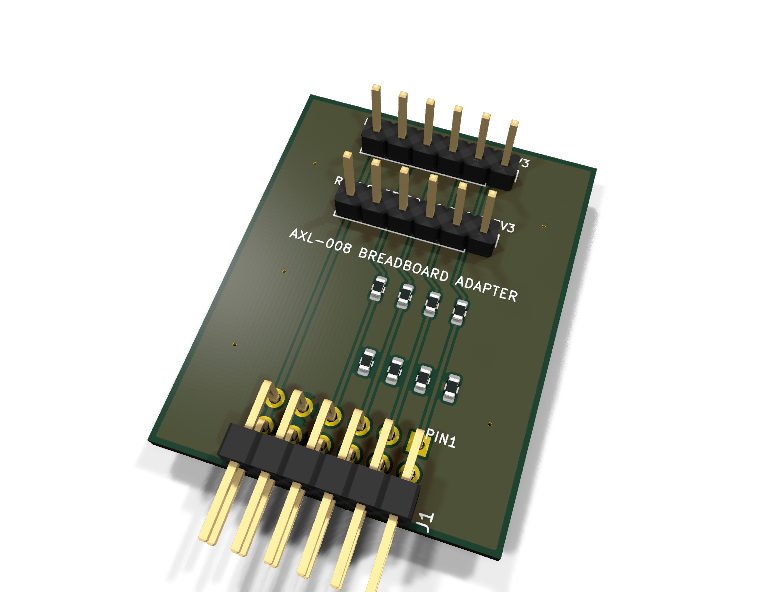
AXL-008 — Breadboard adapter PMOD module
Catalog #8 in the AruviX lab line, level L1. PMOD to labeled 2.54 mm DIP pins so any breadboard circuit reaches the FPGA.
Circuit review & bench-test guide →
Components#
Every placed component, with the reason it is on the board. Extracted directly from the schematic, so this cannot drift from the design.
| Ref | Value | What it does on this board | Part number | Footprint |
|---|---|---|---|---|
J1 |
PMOD PLUG 2x6 | PMOD peripheral plug (Digilent spec 1.2) | not selected generic |
PinHeader_2x06_P2.54mm_Horizontal |
J2 |
ROW A (PMOD 1-6) | Breadboard row A: B1 B2 B3 B4 GND 3V3 (PMOD upper row order) | not selected generic |
PinHeader_1x06_P2.54mm_Vertical |
J3 |
ROW B (PMOD 7-12) | Breadboard row B: B7 B8 B9 B10 GND 3V3 (PMOD lower row order) | not selected generic |
PinHeader_1x06_P2.54mm_Vertical |
R1 |
100R | Series protection between PMOD pin 1 and breadboard row pin B1 | RC0603FR-07100RLYageo Datasheet ↗ |
R_0603_1608Metric |
R2 |
100R | Series protection between PMOD pin 2 and breadboard row pin B2 | RC0603FR-07100RLYageo Datasheet ↗ |
R_0603_1608Metric |
R3 |
100R | Series protection between PMOD pin 3 and breadboard row pin B3 | RC0603FR-07100RLYageo Datasheet ↗ |
R_0603_1608Metric |
R4 |
100R | Series protection between PMOD pin 4 and breadboard row pin B4 | RC0603FR-07100RLYageo Datasheet ↗ |
R_0603_1608Metric |
R5 |
100R | Series protection between PMOD pin 7 and breadboard row pin B7 | RC0603FR-07100RLYageo Datasheet ↗ |
R_0603_1608Metric |
R6 |
100R | Series protection between PMOD pin 8 and breadboard row pin B8 | RC0603FR-07100RLYageo Datasheet ↗ |
R_0603_1608Metric |
R7 |
100R | Series protection between PMOD pin 9 and breadboard row pin B9 | RC0603FR-07100RLYageo Datasheet ↗ |
R_0603_1608Metric |
R8 |
100R | Series protection between PMOD pin 10 and breadboard row pin B10 | RC0603FR-07100RLYageo Datasheet ↗ |
R_0603_1608Metric |
Signals#
Net labels used in the schematic, which are also the names the HDL top level should use.
3V3 B1 B10 B2 B3 B4 B7 B8 B9 GND P1 P10 P2 P3 P4 P7 P8 P9
Production status#
| Schematic ERC | 0 violations |
|---|---|
| PCB layout | complete |
| DRC | 0 violations |
| Fab package | exported (24 gerbers + drill + CPL + BOM) |
| Fabricated | no — design stage only |
Source: boards/lab-modules/axl-008-breadboard
Catalog #8 in the AruviX lab line (../README.md), level L1. PMOD to labeled 2.54 mm DIP pins so any breadboard circuit reaches the FPGA.
Status: schematic generated, ERC clean (0/0), netlist reviewed. PCB layout not started. Not released.
Design#
Trivial by intent — the whole job is an exactly-right netlist, because the silkscreen labels are the schematic net names:
- J1 PMOD plug → 100 Ω series on the 8 signals → two 1×06 pin-header rows (
PinHeader_1x06_P2.54mm_Vertical, MPN TBD) to be placed at breadboard DIP spacing (0.3" row-to-row) at layout. - Net
B<n>= PMOD signal pin n, so the breadboard rows read like the PMOD spec: row A = B1 B2 B3 B4 GND 3V3, row B = B7 B8 B9 B10 GND 3V3. - GND/3V3 pass straight through (no series). No ICs → no decoupling.
| PMOD pin | 1 | 2 | 3 | 4 | 5 | 6 | 7 | 8 | 9 | 10 | 11 | 12 |
|---|---|---|---|---|---|---|---|---|---|---|---|---|
| Net (host) | P1 | P2 | P3 | P4 | GND | 3V3 | P7 | P8 | P9 | P10 | GND | 3V3 |
| Breadboard | B1 | B2 | B3 | B4 | GND | 3V3 | B7 | B8 | B9 | B10 | GND | 3V3 |
Regenerate#
python3 generate_design.pyRemaining for release#
- [ ] PCB layout (rows on 0.3" DIP spacing), silkscreen = net names, DRC
- [ ] Pin-header MPN
- [ ] BOM export and availability check, design-review checklist