Actuator modules
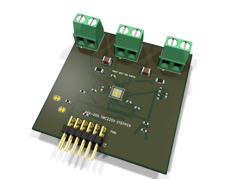
AXA-006 — TMC2209 stepper driver PMOD module
Catalog #6 in the AruviX actuator line, level L3. TMC2209 (Analog Devices/Trinamic), soldered — deliberately not a socketed step-stick: the schematic is part of the curriculum.
Circuit review & bench-test guide →
Components#
Every placed component, with the reason it is on the board. Extracted directly from the schematic, so this cannot drift from the design.
| Ref | Value | What it does on this board | Part number | Footprint |
|---|---|---|---|---|
C1 |
22uF 35V X7R | VS bulk reservoir (chopper ripple) | not selected Murata |
C_1210_3225Metric |
C2 |
22uF 35V X7R | VS bulk reservoir | not selected Murata |
C_1210_3225Metric |
C3 |
100nF 50V X7R | VS high-frequency decoupling at the driver | GRM188R71H104KA93DMurata |
C_0603_1608Metric |
C4 |
100nF 50V X7R | Charge pump reservoir VCP->VS (datasheet standard application) | GRM188R71H104KA93DMurata |
C_0603_1608Metric |
C5 |
22nF 50V X7R | Charge pump flying capacitor CPO-CPI | GRM188R71H223KA01DMurata |
C_0603_1608Metric |
C6 |
4.7uF 10V X5R | 5VOUT regulator output capacitor (datasheet: 2.2-4.7 uF) | GRM188R61A475KE15DMurata |
C_0603_1608Metric |
C7 |
100nF 16V X7R | VREF filter capacitor | GRM188R71C104KA01DMurata |
C_0603_1608Metric |
C8 |
100nF 16V X7R | VCC_IO decoupling | GRM188R71C104KA01DMurata |
C_0603_1608Metric |
J1 |
PMOD PLUG 2x6 | PMOD peripheral plug (Digilent spec 1.2) | not selected generic |
PinHeader_2x06_P2.54mm_Horizontal |
J2 |
VS IN 4.75-29V | Motor supply input: 1 VS (4.75-29 V), 2 GND (joins PMOD GND here) | not selected Phoenix Contact |
TerminalBlock_Phoenix_MKDS-1,5-2-5.08_1x02_P5.08mm_Horizontal |
J3 |
MOTOR A | Motor phase A: 1 OA1, 2 OA2 | not selected Phoenix Contact |
TerminalBlock_Phoenix_MKDS-1,5-2-5.08_1x02_P5.08mm_Horizontal |
J4 |
MOTOR B | Motor phase B: 1 OB1, 2 OB2 | not selected Phoenix Contact |
TerminalBlock_Phoenix_MKDS-1,5-2-5.08_1x02_P5.08mm_Horizontal |
JP1 |
MS1=GND | MS1/AD0 strap, bridged to GND (cut + bodge to 3V3 for address/microstep change) | — | SolderJumper-2_P1.3mm_Bridged_RoundedPad1.0x1.5mm |
JP2 |
MS2=GND | MS2/AD1 strap, bridged to GND | — | SolderJumper-2_P1.3mm_Bridged_RoundedPad1.0x1.5mm |
R1 |
10k | ENN pull-up: driver disabled until the host drives ENN low | RC0603FR-0710KLYageo Datasheet ↗ |
R_0603_1608Metric |
R2 |
100R | Series protection on the driver-driven DIAG line | RC0603FR-07100RLYageo Datasheet ↗ |
R_0603_1608Metric |
R3 |
100R | Series protection on the driver-driven INDEX line | RC0603FR-07100RLYageo Datasheet ↗ |
R_0603_1608Metric |
R4 |
1k | Single-wire UART: host TX through 1k (Trinamic convention) | RC0603FR-071KLYageo Datasheet ↗ |
R_0603_1608Metric |
R5 |
100R | Host RX senses the UART wire (100R per module-driven line rule) | RC0603FR-07100RLYageo Datasheet ↗ |
R_0603_1608Metric |
R6 |
0.11R 1% 1206 | Phase A sense resistor (RDSonSense off): sets full-scale current | not selected Bourns Datasheet ↗ |
R_1206_3216Metric |
R7 |
0.11R 1% 1206 | Phase B sense resistor | not selected Bourns Datasheet ↗ |
R_1206_3216Metric |
R8 |
10k | VREF divider top: 5VOUT/2 = 2.5 V full analog scale | RC0603FR-0710KLYageo Datasheet ↗ |
R_0603_1608Metric |
R9 |
10k | VREF divider bottom | RC0603FR-0710KLYageo Datasheet ↗ |
R_0603_1608Metric |
U1 |
TMC2209-LA | 2-phase stepper driver, 2.8 A peak, stealthChop2, single-wire UART, StallGuard4 | TMC2209-LA-TAnalog Devices (Trinamic) Datasheet ↗ |
VQFN-28-1EP_5x5mm_P0.5mm_EP3.7x3.7mm_ThermalVias |
Signals#
Net labels used in the schematic, which are also the names the HDL top level should use.
3V3 CPI CPO DIAG DIR ENN GND INDEX MS1 MS2 OA1 OA2 OB1 OB2 PDN_UART SENSE_A SENSE_B STEP TMC_DIAG TMC_INDEX UART_RX UART_TX V5OUT VCP VMOT VREF
Production status#
| Schematic ERC | 0 violations |
|---|---|
| PCB layout | complete |
| DRC | 0 violations |
| Fab package | exported (24 gerbers + drill + CPL + BOM) |
| Fabricated | no — design stage only |
Source: boards/actuator-modules/axa-006-stepper
Catalog #6 in the AruviX actuator line (../README.md), level L3. TMC2209 (Analog Devices/Trinamic), soldered — deliberately not a socketed step-stick: the schematic is part of the curriculum.
Status: schematic generated, ERC clean (0/0), netlist reviewed. PCB layout not started. Not released.
What it teaches#
Step/dir motion profiles (trapezoid/S-curve acceleration ramps generated in hardware by step_profile) plus the serial-config lesson on top: the Trinamic single-wire UART for IRUN/IHOLD current scaling, microstep resolution, stealthChop/spreadCycle selection, and StallGuard4 sensorless load measurement via DIAG.
Design#
- TMC2209-LA-T, VQFN-28. Datasheet: rev 1.09 standard application.
- Motor power (VS, 4.75–29 V) enters on the J2 screw terminal only. Bulk 2× 22 µF 35 V 1210 (MPN TBD — confirm GRM32ER7YA226KA12L availability) + 100 nF 50 V. Grounds join on the module.
- Charge pump: 22 nF flying cap CPO–CPI, 100 nF VCP→VS (per datasheet).
- 5VOUT: 4.7 µF to GND (datasheet range 2.2–4.7 µF). VCC_IO = PMOD 3V3 with 100 nF.
- Current setting: 2× 0.11 Ω 1% 1206 sense resistors (MPN TBD, e.g. Bourns CRL1206-FW-R110ELF). VREF is strapped to 2.5 V (10k/10k divider from 5VOUT + 100 nF filter) = full analog scale. With vsense = 0 that is I_rms(max) = (325 mV / 0.13 Ω) / √2 ≈ 1.77 A rms — scale down with UART
IRUNbefore running small motors (that is the UART exercise). - ENN has a 10 k pull-up: driver disabled until the host drives it low.
- STDBY (checked against the datasheet: active-high standby, internal 100 k pull-down) is tied to GND — always awake. SPREAD tied to GND (stealthChop default; UART can override). CLK tied to GND (internal oscillator).
- MS1/MS2 (UART address / standalone microstep straps): solder jumpers JP1/JP2, bridged to GND by default → UART address 0, 1/8 microstep in standalone. Cut and bodge to 3V3 to change.
- Single-wire UART (Trinamic convention): host TX → R4 1 k → PDN_UART; host RX senses the wire through R5 100 Ω. During the TMC2209's reply the 1 k isolates the (idle-high) host TX driver so the driver wins the wire; the host reads back its own transmit as an echo — the fabric UART must discard the echo before parsing the reply datagram.
- DIAG and INDEX are driver-driven and pass 100 Ω (line rule); DIAG doubles as the StallGuard output — the fault/sense line the actuator line requires.
| PMOD pin | 1 | 2 | 3 | 4 | 5 | 6 | 7 | 8 | 9 | 10 | 11 | 12 |
|---|---|---|---|---|---|---|---|---|---|---|---|---|
| Net | STEP | DIR | ENN | DIAG | GND | 3V3 | UART_TX | INDEX | UART_RX | NC | GND | 3V3 |
(Deviation from the catalog sketch: pin 9 carries UART_RX so the host can sense the single-wire bus — TX-through-1k alone cannot read replies.)
Regenerate#
python3 generate_design.pyRemaining for release#
- [ ] PCB layout (20 × 40 mm actuator outline, EP thermal vias, sense-resistor Kelvin routing), DRC, fab outputs
- [ ]
hdl/:step_profile+ TMC UART master (echo discard, CRC8), self-checking testbenches, ECP5 demo - [ ] Confirm bulk-cap and sense-resistor MPNs, BOM export, design-review checklist