I/O modules
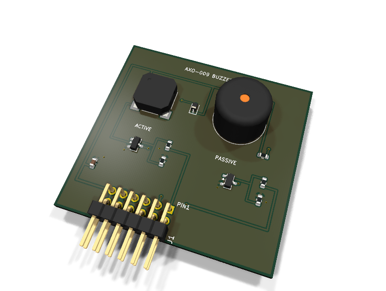
AXO-009 — buzzer pack (active + passive) PMOD module
Catalog #9 in the AruviX output line, level L2 (GPIO/PWM). Two sound sources on one Type 1 PMOD, and the contrast is the lesson: the active buzzer has its own oscillator, the passive piezo is yours to drive.
Circuit review & bench-test guide →
Components#
Every placed component, with the reason it is on the board. Extracted directly from the schematic, so this cannot drift from the design.
| Ref | Value | What it does on this board | Part number | Footprint |
|---|---|---|---|---|
BZ1 |
ACTIVE 3.3V | Active magnetic buzzer: built-in oscillator, fixed pitch | not selected TBD |
MagneticBuzzer_Kobitone_254-EMB84Q-RO |
BZ2 |
PIEZO PASSIVE | Passive piezo disc: no oscillator, host PWM sets the pitch | not selected TBD |
Buzzer_12x9.5RM7.6 |
C1 |
100nF 16V X7R | Rail decoupling | GRM188R71C104KA01DMurata |
C_0603_1608Metric |
D1 |
1N4148WS | Flyback clamp across the magnetic buzzer coil (cathode to 3V3) | 1N4148WS,115Nexperia Datasheet ↗ |
D_SOD-323 |
J1 |
PMOD PLUG 2x6 | PMOD peripheral plug (Digilent spec 1.2) | not selected generic |
PinHeader_2x06_P2.54mm_Horizontal |
Q1 |
AO3400A | Active-buzzer low-side switch | AO3400AAlpha & Omega Semiconductor Datasheet ↗ |
SOT-23 |
Q2 |
AO3400A | Piezo low-side switch (PWM-driven) | AO3400AAlpha & Omega Semiconductor Datasheet ↗ |
SOT-23 |
R1 |
1k | Q1 gate series resistor from PMOD pin 1 | RC0603FR-071KLYageo Datasheet ↗ |
R_0603_1608Metric |
R2 |
10k | Q1 gate pull-down: buzzer silent until the host drives BUZZ_ACT | RC0603FR-0710KLYageo Datasheet ↗ |
R_0603_1608Metric |
R3 |
1k | Q2 gate series resistor from PMOD pin 2 | RC0603FR-071KLYageo Datasheet ↗ |
R_0603_1608Metric |
R4 |
10k | Q2 gate pull-down: piezo silent until the host drives BUZZ_PWM | RC0603FR-0710KLYageo Datasheet ↗ |
R_0603_1608Metric |
R5 |
1k | Bleed resistor in parallel with the piezo (capacitive load: discharge path, no flyback) | RC0603FR-071KLYageo Datasheet ↗ |
R_0603_1608Metric |
Signals#
Net labels used in the schematic, which are also the names the HDL top level should use.
3V3 ACT_SW BUZZ_ACT BUZZ_ACT_G BUZZ_PWM BUZZ_PWM_G GND PZ_SW
Production status#
| Schematic ERC | 0 violations |
|---|---|
| PCB layout | complete |
| DRC | 0 violations |
| Fab package | exported (24 gerbers + drill + CPL + BOM) |
| Fabricated | no — design stage only |
Source: boards/io-modules/axo-009-buzzer
Catalog #9 in the AruviX output line (../README.md), level L2 (GPIO/PWM). Two sound sources on one Type 1 PMOD, and the contrast is the lesson: the active buzzer has its own oscillator, the passive piezo is yours to drive.
Status: schematic generated, ERC clean (0/0), netlist reviewed. PCB layout not started. Not released.
What it teaches#
- BZ1, active magnetic buzzer (
BUZZ_ACT, PMOD 1): drive the pin high and it beeps at its fixed factory pitch — the on/off lesson (alarms, status beeps). - BZ2, passive piezo (
BUZZ_PWM, PMOD 2): no oscillator inside — the FPGA is the oscillator. PWM frequency = pitch, duty = loudness-ish. Melodies, sirens, and a first DDS-adjacent timing exercise. Useful range ~200 Hz–10 kHz; loudest near the ~4 kHz resonance.
Design#
- Each channel is a low-side AO3400A N-FET switch (SOT-23): load+ → 3V3, load− → drain, source → GND, gate ← 1 kΩ from the PMOD pin, 10 kΩ gate pull-down so both stay silent until the host drives them.
- Inductive vs capacitive load — documented on the sheet: the magnetic buzzer is a coil, so D1 (1N4148WS, SOD-323) clamps the turn-off flyback spike (cathode to 3V3). The piezo is a capacitive disc — no flyback needed; instead R5 (1 kΩ) in parallel bleeds its stored charge so it does not stay biased between notes.
- 100 nF rail decoupling; PWR_FLAGs on 3V3/GND. Both lines host-driven, so the 100 Ω series-resistor rule for module-driven lines does not apply.
- Footprints are stock:
Buzzer_Beeper:MagneticBuzzer_Kobitone_254-EMB84Q-RO(BZ1) andBuzzer_Beeper:Buzzer_12x9.5RM7.6(BZ2). Orderable parts are stillTBD:a 3.3 V active magnetic buzzer in the EMB84Q footprint and a 12 mm / 7.6 mm-pitch passive piezo; pin before release.
| PMOD pin | 1 | 2 | 3 | 4 | 5 | 6 | 7 | 8 | 9 | 10 | 11 | 12 |
|---|---|---|---|---|---|---|---|---|---|---|---|---|
| Net | BUZZ_ACT | BUZZ_PWM | NC | NC | GND | 3V3 | NC | NC | NC | NC | GND | 3V3 |
Regenerate#
python3 generate_design.pyRemaining for release#
- [ ] Pin the
TBD:buzzer MPNs (verify 3.3 V rated active buzzer current < PMOD budget) and re-check footprints against the chosen parts - [ ] PCB layout, DRC, fab outputs
- [ ]
hdl/: tone/PWM core, melody sequencer demo, testbench - [ ] BOM export and availability check, design-review checklist