Sensor modules
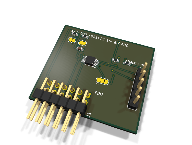
AXS-032 — ADS1115 16-bit precision ADC PMOD module
Catalog #32, level L3 (I2C, precision analog).
Circuit review & bench-test guide →
Components#
Every placed component, with the reason it is on the board. Extracted directly from the schematic, so this cannot drift from the design.
| Ref | Value | What it does on this board | Part number | Footprint |
|---|---|---|---|---|
C1 |
100nF 16V X7R | VDD decoupling | GRM188R71C104KA01DMurata |
C_0603_1608Metric |
J1 |
PMOD PLUG 2x6 | PMOD peripheral plug (Digilent spec 1.2) | not selected generic |
PinHeader_2x06_P2.54mm_Horizontal |
J2 |
ANALOG IN | Analog input header: AIN0-AIN3 and GND reference | — | PinHeader_1x05_P2.54mm_Vertical |
JP1 |
SDA PULL-UP | Cut to remove the SDA pull-up when chaining modules | — | SolderJumper-2_P1.3mm_Bridged_RoundedPad1.0x1.5mm |
JP2 |
SCL PULL-UP | Cut to remove the SCL pull-up when chaining modules | — | SolderJumper-2_P1.3mm_Bridged_RoundedPad1.0x1.5mm |
JP3 |
ADDR 0x48/0x49 | I2C address select: 1-2 ADDR to GND 0x48 (default), 2-3 ADDR to VDD 0x49 | — | SolderJumper-3_P1.3mm_Bridged12_RoundedPad1.0x1.5mm |
R1 |
4.7k | I2C SDA pull-up | RC0603FR-074K7LYageo Datasheet ↗ |
R_0603_1608Metric |
R2 |
4.7k | I2C SCL pull-up | RC0603FR-074K7LYageo Datasheet ↗ |
R_0603_1608Metric |
R3 |
10k | ALERT/RDY open-drain pull-up | RC0603FR-0710KLYageo Datasheet ↗ |
R_0603_1608Metric |
R4 |
100R | Series protection on the ADC-driven ALERT/RDY line | RC0603FR-07100RLYageo Datasheet ↗ |
R_0603_1608Metric |
U1 |
ADS1115 | 16-bit 4-channel sigma-delta ADC with PGA and comparator | ADS1115IDGSRTexas Instruments Datasheet ↗ |
TSSOP-10_3x3mm_P0.5mm |
Signals#
Net labels used in the schematic, which are also the names the HDL top level should use.
3V3 ADC_RDY ADC_RDY_RAW ADDR AIN0 AIN1 AIN2 AIN3 GND SCL SCL_PU SDA SDA_PU
Production status#
| Schematic ERC | 0 violations |
|---|---|
| PCB layout | complete |
| DRC | 0 violations |
| Fab package | exported (24 gerbers + drill + CPL + BOM) |
| Fabricated | no — design stage only |
Source: boards/sensor-modules/axs-032-ads1115
Catalog #32 (../README.md), level L3 (I2C, precision analog).
Status: schematic generated, ERC clean (0/0), netlist reviewed. PCB layout not started. Not released.
What it teaches#
Real analog measurement from the FPGA: PGA setup, single-shot vs continuous conversion, and the ALERT/RDY handshake — the general-purpose analog input board for the whole line (potentiometers, LDRs, thermistors, soil probes).
Design#
- TI ADS1115 (TSSOP-10): 4 single-ended / 2 differential inputs on J2 (AIN0–AIN3 + GND), PGA ±256 mV…±6.144 V.
- ALERT/RDY open-drain: 10 kΩ pull-up, 100 Ω series to PMOD 1.
- Address 0x48 (JP3 1-2, default) or 0x49 (2-3); the SDA/SCL address codes are not jumpered — note for multi-module buses.
- Inputs must stay within GND−0.3 V…VDD+0.3 V regardless of PGA gain.
Regenerate / remaining#
python3 generate_design.py — then PCB layout, HDL, BOM check, checklist.