Sensor modules
AXS-011 — Photodiode light sensor PMOD module
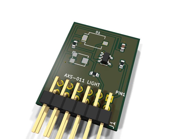
Catalog #11 in the AruviX sensor line, level L1 (GPIO). An ams-OSRAM BPW34S PIN photodiode in photoconductive mode with an LMV7219 comparator and Bourns TC33X threshold trimmer.
Circuit review & bench-test guide →
Components#
Every placed component, with the reason it is on the board. Extracted directly from the schematic, so this cannot drift from the design.
| Ref | Value | What it does on this board | Part number | Footprint |
|---|---|---|---|---|
C1 |
100nF 16V X7R | Comparator supply decoupling | GRM188R71C104KA01DMurata |
C_0603_1608Metric |
D1 |
BPW34S | Silicon PIN photodiode, 850 nm peak, SMD | BPW34Sams-OSRAM Datasheet ↗ |
Osram_BPW34S-SMD |
J1 |
PMOD PLUG 2x6 | PMOD peripheral plug (Digilent spec 1.2) | not selected generic |
PinHeader_2x06_P2.54mm_Horizontal |
R1 |
1M | Photoconductive load: photocurrent x 1M = node voltage | RC0603FR-071MLYageo Datasheet ↗ |
R_0603_1608Metric |
R2 |
100R | Series protection on the module-driven LIGHT line | RC0603FR-07100RLYageo Datasheet ↗ |
R_0603_1608Metric |
R3 |
100R | Series protection on the raw analog node brought out for probing | RC0603FR-07100RLYageo Datasheet ↗ |
R_0603_1608Metric |
RV1 |
10k TRIM | Threshold-set trimmer, 10k, Bourns TC33X | TC33X-2-103EBourns Datasheet ↗ |
Potentiometer_Bourns_TC33X_Vertical |
U1 |
LMV7219M5 | 7 ns push-pull comparator, 2.7-5 V, SOT-23-5 | LMV7219M5XTexas Instruments Datasheet ↗ |
SOT-23-5 |
Signals#
Net labels used in the schematic, which are also the names the HDL top level should use.
3V3 GND LIGHT LIGHT_CMP LIGHT_NODE LIGHT_RAW LIGHT_TH
Production status#
| Schematic ERC | 0 violations |
|---|---|
| PCB layout | complete |
| DRC | 0 violations |
| Fab package | exported (24 gerbers + drill + CPL + BOM) |
| Fabricated | no — design stage only |
Source: boards/sensor-modules/axs-011-photodiode
Catalog #11 in the AruviX sensor line (../README.md), level L1 (GPIO). An ams-OSRAM BPW34S PIN photodiode in photoconductive mode with an LMV7219 comparator and Bourns TC33X threshold trimmer.
Status: schematic generated, ERC clean (0/0), netlist reviewed. PCB layout not started. Not released.
What it teaches#
An analog quantity squeezed through a comparator: light level becomes a node voltage, the trimmer sets the slicing point, and the raw analog node is brought out on PMOD pin 2 so users can scope the truth behind the digital LIGHT bit (and later feed it to an ADC module).
Design#
- BPW34S reverse biased: cathode on 3V3, anode into a 1 MΩ load to GND — photocurrent × 1 MΩ makes the node voltage rise with brightness.
- LMV7219M5 (SOT-23-5, push-pull): +in = photodiode node, −in = RV1 wiper (TC33X-2-103E 10 k across 3V3–GND). LIGHT is high above the threshold.
- 100 Ω series resistors on both module-driven lines: LIGHT (pin 1) and the raw analog node LIGHT_RAW (pin 2). Keep host loading on LIGHT_RAW light — the source impedance is ~1 MΩ.
- MPN is BPW34S (the SMD variant matching the Osram_BPW34S-SMD footprint); 100 nF comparator decoupling.
| PMOD pin | 1 | 2 | 3 | 4 | 5 | 6 | 7 | 8 | 9 | 10 | 11 | 12 |
|---|---|---|---|---|---|---|---|---|---|---|---|---|
| Net | LIGHT | LIGHT_RAW | NC | NC | GND | 3V3 | NC | NC | NC | NC | GND | 3V3 |
Regenerate#
python3 generate_design.pyRemaining for release#
- [ ] PCB layout (20 × 25 mm outline, diode clear of shadowing parts), DRC
- [ ]
hdl/: light-edge events + hysteresis-in-time, testbench, ECP5 demo - [ ] BOM export and availability check, design-review checklist