Actuator modules
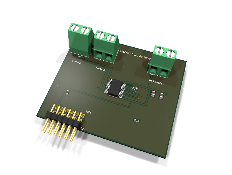
AXA-001 — TB6612FNG dual DC motor driver PMOD module
Catalog #1 in the AruviX actuator line, level L2. Toshiba TB6612FNG dual H-bridge: two brushed DC motors, PWM + direction per channel, standby gate.
Circuit review & bench-test guide →
Components#
Every placed component, with the reason it is on the board. Extracted directly from the schematic, so this cannot drift from the design.
| Ref | Value | What it does on this board | Part number | Footprint |
|---|---|---|---|---|
C1 |
10uF 25V X5R | VM bulk reservoir for motor switching current | GRM21BR61E106KA73LMurata |
C_0805_2012Metric |
C2 |
10uF 25V X5R | VM bulk reservoir for motor switching current | GRM21BR61E106KA73LMurata |
C_0805_2012Metric |
C3 |
100nF 16V X7R | VM high-frequency decoupling at the driver | GRM188R71C104KA01DMurata |
C_0603_1608Metric |
C4 |
100nF 16V X7R | VCC logic decoupling | GRM188R71C104KA01DMurata |
C_0603_1608Metric |
J1 |
PMOD PLUG 2x6 | PMOD peripheral plug (Digilent spec 1.2) | not selected generic |
PinHeader_2x06_P2.54mm_Horizontal |
J3 |
VM IN 2.5-13.5V | Motor supply input: 1 VM (2.5-13.5 V), 2 GND (joins PMOD GND here) | not selected Phoenix Contact |
TerminalBlock_Phoenix_MKDS-1,5-2-5.08_1x02_P5.08mm_Horizontal |
J4 |
MOTOR A | Motor A output: 1 AO1, 2 AO2 | not selected Phoenix Contact |
TerminalBlock_Phoenix_MKDS-1,5-2-5.08_1x02_P5.08mm_Horizontal |
J5 |
MOTOR B | Motor B output: 1 BO1, 2 BO2 | not selected Phoenix Contact |
TerminalBlock_Phoenix_MKDS-1,5-2-5.08_1x02_P5.08mm_Horizontal |
R1 |
10k | STBY pull-down: both bridges disabled until the host drives STBY high | RC0603FR-0710KLYageo Datasheet ↗ |
R_0603_1608Metric |
U1 |
TB6612FNG | Dual DC motor driver H-bridge, 1.2 A per channel, VM 2.5-13.5 V | TB6612FNG,C,8Toshiba Datasheet ↗ |
SSOP-24_5.3x8.2mm_P0.65mm |
Signals#
Net labels used in the schematic, which are also the names the HDL top level should use.
3V3 AIN1 AIN2 AO1 AO2 BIN1 BIN2 BO1 BO2 GND PWMA PWMB STBY VMOT
Production status#
| Schematic ERC | 0 violations |
|---|---|
| PCB layout | complete |
| DRC | 0 violations |
| Fab package | exported (24 gerbers + drill + CPL + BOM) |
| Fabricated | no — design stage only |
Source: boards/actuator-modules/axa-001-dc-motor
Catalog #1 in the AruviX actuator line (../README.md), level L2. Toshiba TB6612FNG dual H-bridge: two brushed DC motors, PWM + direction per channel, standby gate.
Status: schematic generated, ERC clean (0/0), netlist reviewed. PCB layout not started. Not released.
What it teaches#
PWM motor drive in fabric: the PWMx + xIN1/xIN2 truth table (CW / CCW / short-brake / stop) at up to 100 kHz, standby gating, and motor/logic power separation. Pairs with AXA-003 (encoder interface) for the closed-loop PID lab — the line's signature FPGA-beats-MCU demo.
Design#
- TB6612FNG (TB6612FNG,C,8), SSOP-24. 1.2 A per bridge continuous.
- Motor power (VM, 2.5–13.5 V) enters on the J3 screw terminal only — never through the PMOD. Stay inside 2.5–13.5 V; the absolute maximum is 15 V. Grounds join on the module (PGND1/PGND2/GND all to the common ground).
- VCC (logic) is the PMOD 3V3. Decoupling: 2× 10 µF 25 V 0805 + 100 nF on VM, 100 nF on VCC.
- STBY has a 10 kΩ pull-down: both bridges stay safely disabled until the host deliberately drives PMOD pin 9 high.
- Motor outputs: AO1/AO2 → J4, BO1/BO2 → J5 (MKDS 1x02 screw terminals).
- All PMOD lines are host-driven, so no 100 Ω series resistors (the sensor-line rule applies to module-driven lines only).
- Flyback: the H-bridge body diodes are the recirculation path for the motor windings (line flyback rule satisfied internally).
- Line-rule exception (documented): the TB6612FNG has no fault or current-sense output, so this module cannot bring a fault signal back to the PMOD. The high-current slot (AXA-002, DRV8871) covers current limiting.
| PMOD pin | 1 | 2 | 3 | 4 | 5 | 6 | 7 | 8 | 9 | 10 | 11 | 12 |
|---|---|---|---|---|---|---|---|---|---|---|---|---|
| Net | PWMA | AIN1 | AIN2 | PWMB | GND | 3V3 | BIN1 | BIN2 | STBY | NC | GND | 3V3 |
Regenerate#
python3 generate_design.pyRemaining for release#
- [ ] PCB layout (20 × 40 mm actuator outline), DRC, fab outputs
- [ ]
hdl/:pwm_gen+ motor direction controller, testbench, ECP5 demo - [ ] BOM export and availability check, design-review checklist