Sensor modules
AXS-039 — Liquid flow meter carrier PMOD module
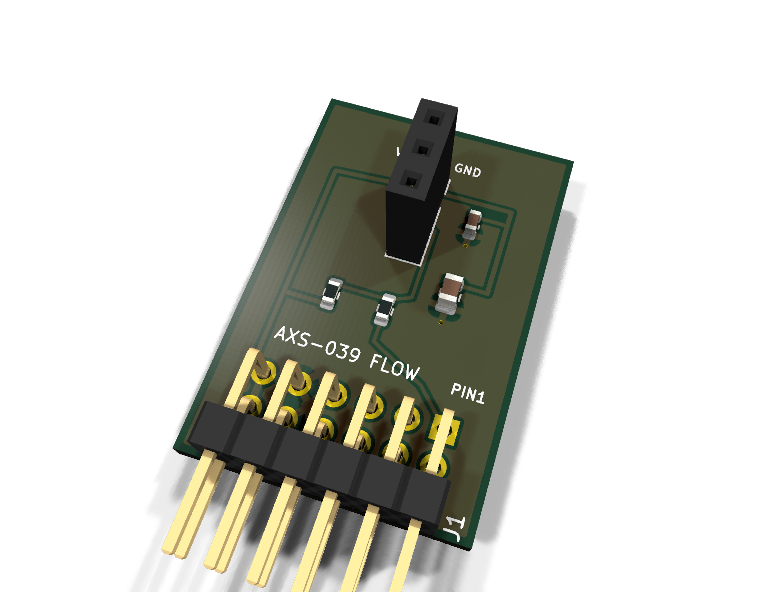
Catalog #39 in the AruviX sensor line, level L2 (GPIO, pulse counting). Socketed carrier (same pattern as AXS-046) for a 3-wire hall-effect turbine flow meter of the YF-S201 class.
Circuit review & bench-test guide →
Components#
Every placed component, with the reason it is on the board. Extracted directly from the schematic, so this cannot drift from the design.
| Ref | Value | What it does on this board | Part number | Footprint |
|---|---|---|---|---|
C1 |
100nF 16V X7R | Socket decoupling | GRM188R71C104KA01DMurata |
C_0603_1608Metric |
C2 |
10uF 10V X5R | Bulk reservoir at the flow-meter socket (cable inductance + hall switching) | GRM21BR61A106KE19LMurata |
C_0805_2012Metric |
J1 |
PMOD PLUG 2x6 | PMOD peripheral plug (Digilent spec 1.2) | not selected generic |
PinHeader_2x06_P2.54mm_Horizontal |
J2 |
FLOW METER SOCKET | Socket for a 3-wire hall turbine flow meter cable, pin order VCC/SIGNAL/GND | not selected generic |
PinSocket_1x03_P2.54mm_Vertical |
R1 |
10k | Pull-up for the meter's open-collector hall output | RC0603FR-0710KLYageo Datasheet ↗ |
R_0603_1608Metric |
R2 |
100R | Series protection on the module-driven FLOW line | RC0603FR-07100RLYageo Datasheet ↗ |
R_0603_1608Metric |
Signals#
Net labels used in the schematic, which are also the names the HDL top level should use.
3V3 FLOW FLOW_RAW GND
Production status#
| Schematic ERC | 0 violations |
|---|---|
| PCB layout | complete |
| DRC | 0 violations |
| Fab package | exported (24 gerbers + drill + CPL + BOM) |
| Fabricated | no — design stage only |
Source: boards/sensor-modules/axs-039-flow
Catalog #39 in the AruviX sensor line (../README.md), level L2 (GPIO, pulse counting). Socketed carrier (same pattern as AXS-046) for a 3-wire hall-effect turbine flow meter of the YF-S201 class.
Status: schematic generated, ERC clean (0/0), netlist reviewed. PCB layout not started. Not released.
What it teaches#
Frequency as a measurand: the turbine's hall sensor pulses at a rate proportional to flow. Count pulses per gate interval, apply the meter's K-factor (YF-S201 class: roughly f ≈ 7.5 × Q with f in Hz and Q in L/min, i.e. ~450 pulses per litre), and calibrate K yourself with a measuring jug — calibration is part of the lesson.
Design#
- J2 is a 1×03 pin socket, pin order VCC / SIGNAL / GND, matching the usual red/yellow/black flow-meter pigtail.
- Check your meter runs at 3.3 V. The classic YF-S201 is specified 5–18 V; use a 3.3 V-capable variant or a unit you have verified at 3V3. Never feed 5 V through the PMOD rail.
- The hall output is open-collector: 10 kΩ pull-up on-module, then a 100 Ω series resistor to PMOD pin 1 (FLOW). Idles high, pulses low.
- 100 nF + 10 µF at the socket (long cable + switching hall sensor).
| PMOD pin | 1 | 2 | 3 | 4 | 5 | 6 | 7 | 8 | 9 | 10 | 11 | 12 |
|---|---|---|---|---|---|---|---|---|---|---|---|---|
| Net | FLOW | NC | NC | NC | GND | 3V3 | NC | NC | NC | NC | GND | 3V3 |
Regenerate#
python3 generate_design.pyRemaining for release#
- [ ] PCB layout (20 × 25 mm outline), DRC, fab outputs
- [ ]
hdl/: gated pulse counter + fixed-point K-factor scaler, testbench - [ ] Pin a 3.3 V-capable meter part number; BOM export, design review