Sensor modules
AXS-026 — Sound trigger PMOD module
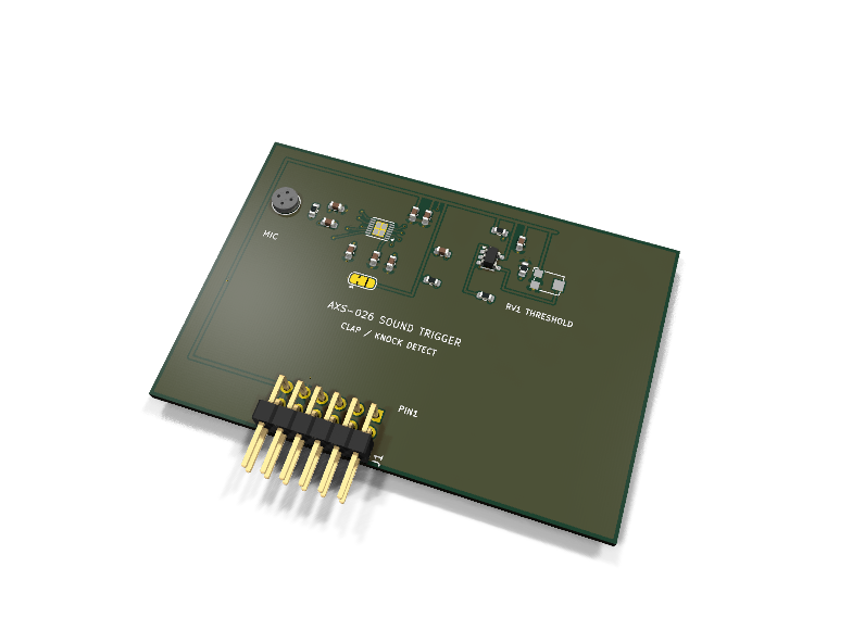
Catalog #26 in the AruviX sensor line, level L1 (GPIO). Electret capsule → MAX9814 microphone amplifier with AGC → LMV7219 comparator with a trimmer-set threshold. The FPGA sees a clean digital SOUND pulse; the raw analog amplifier output is also brought out for scope probing.
Circuit review & bench-test guide →
Components#
Every placed component, with the reason it is on the board. Extracted directly from the schematic, so this cannot drift from the design.
| Ref | Value | What it does on this board | Part number | Footprint |
|---|---|---|---|---|
C1 |
100nF 16V X7R | Microphone AC-coupling capacitor | GRM188R71C104KA01DMurata |
C_0603_1608Metric |
C2 |
470nF 16V X7R | MICBIAS bypass (datasheet typical application) | GRM188R71C474KA88DMurata |
C_0603_1608Metric |
C3 |
470nF 16V X7R | AGC attack/release timing capacitor | GRM188R71C474KA88DMurata |
C_0603_1608Metric |
C4 |
2.2uF 10V X5R | Amplifier DC-offset capacitor (datasheet typical application) | GRM188R61A225KE34DMurata |
C_0603_1608Metric |
C5 |
470nF 16V X7R | Amplifier bias bypass (datasheet typical application) | GRM188R71C474KA88DMurata |
C_0603_1608Metric |
C6 |
1uF 10V X7R | AC coupling from the amplifier into the comparator | GRM188R71A105KA61DMurata |
C_0603_1608Metric |
C7 |
1uF 10V X7R | MAX9814 VDD bypass (datasheet typical application) | GRM188R71A105KA61DMurata |
C_0603_1608Metric |
C8 |
100nF 16V X7R | MAX9814 VDD high-frequency decoupling | GRM188R71C104KA01DMurata |
C_0603_1608Metric |
C9 |
100nF 16V X7R | LMV7219 supply decoupling | GRM188R71C104KA01DMurata |
C_0603_1608Metric |
J1 |
PMOD PLUG 2x6 | PMOD peripheral plug (Digilent spec 1.2) | not selected generic |
PinHeader_2x06_P2.54mm_Horizontal |
JP1 |
GAIN 50/40/60dB | MAX9814 gain strap: 1-2 GND 50 dB (default), 2-3 VDD 40 dB, open 60 dB | — | SolderJumper-3_P1.3mm_Bridged12_RoundedPad1.0x1.5mm |
MK1 |
ELECTRET | Electret condenser microphone capsule, SMT, omnidirectional | CMC-4013-SMT-TRCUI Devices Datasheet ↗ |
CUI_CMC-4013-SMT |
R1 |
2.2k | Electret bias feed from the MAX9814 MICBIAS output | RC0603FR-072K2LYageo Datasheet ↗ |
R_0603_1608Metric |
R2 |
100k | Comparator +in half-rail bias, upper leg | RC0603FR-07100KLYageo Datasheet ↗ |
R_0603_1608Metric |
R3 |
100k | Comparator +in half-rail bias, lower leg | RC0603FR-07100KLYageo Datasheet ↗ |
R_0603_1608Metric |
R4 |
100R | Series protection on the module-driven SOUND line | RC0603FR-07100RLYageo Datasheet ↗ |
R_0603_1608Metric |
R5 |
100R | Series protection on the module-driven SOUND_RAW line | RC0603FR-07100RLYageo Datasheet ↗ |
R_0603_1608Metric |
RV1 |
10k TRIMMER | Threshold-set trimmer across 3V3/GND, wiper to comparator -in | TC33X-2-103EBourns Datasheet ↗ |
Potentiometer_Bourns_TC33X_Vertical |
U1 |
MAX9814 | Microphone amplifier with AGC and low-noise microphone bias | MAX9814ETD+TAnalog Devices Datasheet ↗ |
TDFN-14-1EP_3x3mm_P0.4mm_EP1.78x2.35mm |
U2 |
LMV7219 | 7 ns rail-to-rail comparator, push-pull output | LMV7219M5XTexas Instruments Datasheet ↗ |
SOT-23-5 |
Signals#
Net labels used in the schematic, which are also the names the HDL top level should use.
3V3 AMP_OUT BIAS CG CMP_IN CMP_OUT CT GAIN GND MICBIAS MICIN MIC_P SOUND SOUND_RAW THRESH
Production status#
| Schematic ERC | 0 violations |
|---|---|
| PCB layout | complete |
| DRC | 0 violations |
| Fab package | exported (24 gerbers + drill + CPL + BOM) |
| Fabricated | no — design stage only |
Source: boards/sensor-modules/axs-026-sound-trigger
Catalog #26 in the AruviX sensor line (../README.md), level L1 (GPIO). Electret capsule → MAX9814 microphone amplifier with AGC → LMV7219 comparator with a trimmer-set threshold. The FPGA sees a clean digital SOUND pulse; the raw analog amplifier output is also brought out for scope probing.
Status: schematic generated, ERC clean (0/0), netlist reviewed. PCB layout not started. Not released.
What it teaches#
The simplest possible sensor contract: a GPIO edge. Debouncing/re-trigger suppression in fabric, pulse stretching, and — via SOUND_RAW on a scope — what the comparator actually thresholds. The AGC makes the trigger respond to transients (claps, knocks) rather than absolute loudness.
Design#
- CUI CMC-4013-SMT electret capsule, biased from the MAX9814's low-noise MICBIAS output through 2.2 kΩ (datasheet typical application), AC-coupled 100 nF into MICIN.
- MAX9814ETD+ (TDFN-14) per the datasheet typical application: 470 nF on MICBIAS, CT and BIAS, 2.2 µF on CG, 1 µF + 100 nF on VDD. SHDN and TH to 3V3; A/R strapped to GND (attack:release 1:500 — fast release suits trigger use).
- Gain strap JP1 (3-pad solder jumper): 1-2 bridged = 50 dB (default), 2-3 = 40 dB, both open = 60 dB.
- LMV7219M5 comparator: +in is the 1 µF AC-coupled amp output biased to half-rail by 2 × 100 kΩ; −in is the wiper of Bourns TC33X 10 kΩ trimmer RV1. Push-pull output, no pull-up needed.
- Module-driven
SOUNDandSOUND_RAWpass 100 Ω series resistors.
| PMOD pin | 1 | 2 | 3 | 4 | 5 | 6 | 7 | 8 | 9 | 10 | 11 | 12 |
|---|---|---|---|---|---|---|---|---|---|---|---|---|
| Net | SOUND | SOUND_RAW | NC | NC | GND | 3V3 | NC | NC | NC | NC | GND | 3V3 |
Regenerate#
python3 generate_design.pyRemaining for release#
- [ ] PCB layout, DRC, fab outputs
- [ ]
hdl/: edge detector + pulse stretcher, ECP5 demo - [ ] BOM export and availability check, design-review checklist