Sensor modules
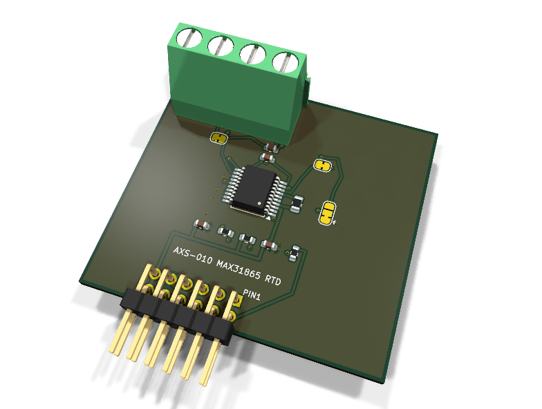
AXS-010 — MAX31865 PT100 RTD front-end PMOD module
Catalog #10 in the AruviX sensor line, level L3 (SPI). A PT100 resistance-temperature-detector front end: the MAX31865 converts the RTD/RREF resistance ratio to a 15-bit result, supporting 2/3/4-wire sensor hookups.
Circuit review & bench-test guide →
Components#
Every placed component, with the reason it is on the board. Extracted directly from the schematic, so this cannot drift from the design.
| Ref | Value | What it does on this board | Part number | Footprint |
|---|---|---|---|---|
C1 |
100nF 16V X7R | U1 VDD (analog supply) decoupling | GRM188R71C104KA01DMurata |
C_0603_1608Metric |
C2 |
100nF 16V X7R | U1 DVDD (digital supply) decoupling | GRM188R71C104KA01DMurata |
C_0603_1608Metric |
C3 |
100nF 16V X7R | Differential filter across the RTD sense inputs (datasheet typical application) | GRM188R71C104KA01DMurata |
C_0603_1608Metric |
C4 |
10nF 50V C0G | Filter across the RTD force leads | GRM1885C1H103JA01DMurata |
C_0603_1608Metric |
J1 |
PMOD PLUG 2x6 | PMOD peripheral plug (Digilent spec 1.2) | not selected generic |
PinHeader_2x06_P2.54mm_Horizontal |
J2 |
PT100 RTD | RTD terminal: 1 FORCE+, 2 SENSE+ (RTDIN+), 3 SENSE- (RTDIN-), 4 FORCE- | MKDS 1,5/4-5,08 (1715048)Phoenix Contact |
TerminalBlock_Phoenix_MKDS-1,5-4-5.08_1x04_P5.08mm_Horizontal |
JP3 |
2/3-WIRE + | Bridges FORCE+ to RTDIN+ for 2/3-wire RTDs; cut for true 4-wire sensing | — | SolderJumper-2_P1.3mm_Bridged_RoundedPad1.0x1.5mm |
JP4 |
2-WIRE - | Bridges RTDIN- to FORCE- for 2-wire RTDs; cut for 3-wire and 4-wire sensing | — | SolderJumper-2_P1.3mm_Bridged_RoundedPad1.0x1.5mm |
JP5 |
FORCE2 SEL | FORCE2 per datasheet: 1-2 GND for 2/4-wire (default), 2-3 FORCE+ for 3-wire | — | SolderJumper-3_P1.3mm_Bridged12_RoundedPad1.0x1.5mm |
R1 |
400R 0.1% | RTD reference resistor, 400R 0.1% 25ppm (PT100 range) | not selected Panasonic Datasheet ↗ |
R_0805_2012Metric |
R2 |
100R | Series protection on the sensor-driven MISO line | RC0603FR-07100RLYageo Datasheet ↗ |
R_0603_1608Metric |
R3 |
100R | Series protection on the sensor-driven ~DRDY line (push-pull) | RC0603FR-07100RLYageo Datasheet ↗ |
R_0603_1608Metric |
R4 |
10k | ~CS idle pull-up so the SPI port stays deselected until the host drives it | RC0603FR-0710KLYageo Datasheet ↗ |
R_0603_1608Metric |
U1 |
MAX31865 | RTD-to-digital converter, 15-bit ratiometric, 2/3/4-wire PT100/PT1000 | MAX31865AAP+Analog Devices Datasheet ↗ |
SSOP-20_5.3x7.2mm_P0.65mm |
Signals#
Net labels used in the schematic, which are also the names the HDL top level should use.
3V3 CS_N DRDY_N FORCE2 FORCE_N FORCE_P GND MISO MOSI REFIN_N RTDIN_N RTDIN_P RTD_DRDY_N RTD_SDO SCK VBIAS
Production status#
| Schematic ERC | 0 violations |
|---|---|
| PCB layout | complete |
| DRC | 0 violations |
| Fab package | exported (24 gerbers + drill + CPL + BOM) |
| Fabricated | no — design stage only |
Source: boards/sensor-modules/axs-010-max31865
Catalog #10 in the AruviX sensor line (../README.md), level L3 (SPI). A PT100 resistance-temperature-detector front end: the MAX31865 converts the RTD/RREF resistance ratio to a 15-bit result, supporting 2/3/4-wire sensor hookups.
Status: schematic generated, ERC clean (0/0), netlist reviewed. PCB layout not started. Not released.
What it teaches#
An SPI master (modes 1/3, ≤5 MHz) with read and write register access (configuration, fault thresholds), ~DRDY-paced conversions, and ratiometric fixed-point math: temperature comes from R_RTD = ADC/32768 × R_REF plus a Callendar–Van Dusen linearization — the heaviest arithmetic lesson in the SPI group.
Design#
- MAX31865AAP+ (SSOP-20). VDD and DVDD on 3V3, 100 nF each.
- Reference: R1 400 Ω 0.1 % 0805 between REFIN+ and REFIN− per the datasheet PT100 topology (BIAS→REFIN+, ISENSOR→REFIN−). MPN
TBD: confirm ERA-6AEB4000V(Panasonic precision chip R). - RTD terminal: J2 Phoenix MKDS 1,5/4-5,08 (footprint
TerminalBlock_Phoenix_MKDS-1,5-4-5.08_1x04_P5.08mm_Horizontal— the spec'd..._1x04_P5.08mm_...name without the-5.08infix does not exist in the stock library; this is the same block at 5.08 mm pitch). Terminals: 1 FORCE+, 2 SENSE+ (RTDIN+), 3 SENSE− (RTDIN−), 4 FORCE−. - Wire-count jumpers (default as shipped = 2-wire):
- JP3 (bridged): FORCE+ ↔ RTDIN+ — keep for 2/3-wire, cut for 4-wire.
- JP4 (bridged): RTDIN− ↔ FORCE− — keep for 2-wire, cut for 3/4-wire.
- JP5 (3-way): FORCE2 → 1-2 GND for 2/4-wire (default, per datasheet), 2-3 FORCE+ for 3-wire.
- Filters: 100 nF across RTDIN+/RTDIN−, 10 nF across FORCE+/FORCE−.
- Sensor-driven SDO and ~DRDY (push-pull) pass 100 Ω series resistors; 10 kΩ pull-up on ~CS.
| PMOD pin | 1 | 2 | 3 | 4 | 5 | 6 | 7 | 8 | 9 | 10 | 11 | 12 |
|---|---|---|---|---|---|---|---|---|---|---|---|---|
| Net | ~CS | MOSI | MISO | SCK | GND | 3V3 | ~DRDY | NC | NC | NC | GND | 3V3 |
Regenerate#
python3 generate_design.pyreports/erc.rpt is the last kicad-cli ERC run.
Remaining for release#
- [ ] Confirm the RREF orderable part (400 Ω 0.1 % 25 ppm 0805)
- [ ] PCB layout (keep the analog front end away from the PMOD bus), DRC, fab outputs
- [ ]
hdl/: SPI master core, MAX31865 controller, CVD linearization, testbench, ECP5 demo - [ ] BOM export and availability check, design-review checklist