Lab modules
AXL-007 — I2C hub PMOD module (TCA9548A)
Catalog #7 in the AruviX lab line, level L3. Solves I2C address clashes when a class chains many identical modules — and is the "why muxes exist" lesson.
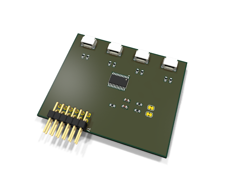
Circuit review & bench-test guide →
Components#
Every placed component, with the reason it is on the board. Extracted directly from the schematic, so this cannot drift from the design.
| Ref | Value | What it does on this board | Part number | Footprint |
|---|---|---|---|---|
C1 |
100nF 16V X7R | U1 decoupling | GRM188R71C104KA01DMurata |
C_0603_1608Metric |
C2 |
1uF 10V X7R | Module bulk decoupling | GRM188R71A105KA61DMurata |
C_0603_1608Metric |
J1 |
PMOD PLUG 2x6 | PMOD peripheral plug (Digilent spec 1.2) | not selected generic |
PinHeader_2x06_P2.54mm_Horizontal |
J2 |
QWIIC CH0 | Qwiic socket on mux channel 0: 1 GND, 2 3V3, 3 SDA, 4 SCL | SM04B-SRSS-TB(LF)(SN)JST Datasheet ↗ |
JST_SH_SM04B-SRSS-TB_1x04-1MP_P1.00mm_Horizontal |
J3 |
QWIIC CH1 | Qwiic socket on mux channel 1: 1 GND, 2 3V3, 3 SDA, 4 SCL | SM04B-SRSS-TB(LF)(SN)JST Datasheet ↗ |
JST_SH_SM04B-SRSS-TB_1x04-1MP_P1.00mm_Horizontal |
J4 |
QWIIC CH2 | Qwiic socket on mux channel 2: 1 GND, 2 3V3, 3 SDA, 4 SCL | SM04B-SRSS-TB(LF)(SN)JST Datasheet ↗ |
JST_SH_SM04B-SRSS-TB_1x04-1MP_P1.00mm_Horizontal |
J5 |
QWIIC CH3 | Qwiic socket on mux channel 3: 1 GND, 2 3V3, 3 SDA, 4 SCL | SM04B-SRSS-TB(LF)(SN)JST Datasheet ↗ |
JST_SH_SM04B-SRSS-TB_1x04-1MP_P1.00mm_Horizontal |
JP1 |
SDA PULL-UP | Cut when the host or another chained module provides the upstream SDA pull-up | — | SolderJumper-2_P1.3mm_Bridged_RoundedPad1.0x1.5mm |
JP2 |
SCL PULL-UP | Cut when the host or another chained module provides the upstream SCL pull-up | — | SolderJumper-2_P1.3mm_Bridged_RoundedPad1.0x1.5mm |
R1 |
4.7k | Upstream SDA pull-up | RC0603FR-074K7LYageo Datasheet ↗ |
R_0603_1608Metric |
R2 |
4.7k | Upstream SCL pull-up | RC0603FR-074K7LYageo Datasheet ↗ |
R_0603_1608Metric |
R3 |
4.7k | Channel 0 SDA pull-up (fixed: a deselected segment floats otherwise) | RC0603FR-074K7LYageo Datasheet ↗ |
R_0603_1608Metric |
R4 |
4.7k | Channel 0 SCL pull-up (fixed) | RC0603FR-074K7LYageo Datasheet ↗ |
R_0603_1608Metric |
R5 |
4.7k | Channel 1 SDA pull-up (fixed: a deselected segment floats otherwise) | RC0603FR-074K7LYageo Datasheet ↗ |
R_0603_1608Metric |
R6 |
4.7k | Channel 1 SCL pull-up (fixed) | RC0603FR-074K7LYageo Datasheet ↗ |
R_0603_1608Metric |
R7 |
4.7k | Channel 2 SDA pull-up (fixed: a deselected segment floats otherwise) | RC0603FR-074K7LYageo Datasheet ↗ |
R_0603_1608Metric |
R8 |
4.7k | Channel 2 SCL pull-up (fixed) | RC0603FR-074K7LYageo Datasheet ↗ |
R_0603_1608Metric |
R9 |
4.7k | Channel 3 SDA pull-up (fixed: a deselected segment floats otherwise) | RC0603FR-074K7LYageo Datasheet ↗ |
R_0603_1608Metric |
R10 |
4.7k | Channel 3 SCL pull-up (fixed) | RC0603FR-074K7LYageo Datasheet ↗ |
R_0603_1608Metric |
R11 |
10k | ~RESET pull-up: hub out of reset until the host drives PMOD 2 low | RC0603FR-0710KLYageo Datasheet ↗ |
R_0603_1608Metric |
U1 |
TCA9548APWR | 8-channel I2C switch with reset, address 0x70 | TCA9548APWRTexas Instruments Datasheet ↗ |
TSSOP-24_4.4x7.8mm_P0.65mm |
Signals#
Net labels used in the schematic, which are also the names the HDL top level should use.
3V3 GND RESET_N SC0 SC1 SC2 SC3 SCL SCL_PU SD0 SD1 SD2 SD3 SDA SDA_PU
Production status#
| Schematic ERC | 0 violations |
|---|---|
| PCB layout | complete |
| DRC | not run |
| Fab package | not exported |
| Fabricated | no — design stage only |
Source: boards/lab-modules/axl-007-i2c-hub
Catalog #7 in the AruviX lab line (../README.md), level L3. Solves I2C address clashes when a class chains many identical modules — and is the "why muxes exist" lesson.
Status: schematic generated, ERC clean (0/0), netlist reviewed. PCB layout not started. Not released.
What it teaches#
Write one control byte to 0x70 to select a channel, then address the device behind it as if it were alone on the bus. Two same-address sensors on two channels is the classic demo.
Design#
- TCA9548APWR (TSSOP-24, stock symbol + footprint verified).
- Upstream: PMOD Type 6 extended (SCL/SDA on 3/4, repeated on 9/10) with the standard jumpered 4.7 kΩ pull-ups (JP1/JP2). ~RESET is host-driven directly on PMOD 2 with a 10 kΩ default-run pull-up.
- Downstream: mux channels 0–3 feed 4× Qwiic sockets (JST
SM04B-SRSS-TB, stock footprint verified; pinout 1 GND, 2 3V3, 3 SDA, 4 SCL). Each channel carries its own fixed 4.7 kΩ pull-up pair — a deselected mux segment is electrically floating and cannot borrow the upstream pull-ups; without per-segment pull-ups the bus glitches on every channel switch (documented on the schematic as the lesson). - A0–A2 strapped to GND → address 0x70.
- Channels 4–7:
no_connect, unused in rev 1 (four Qwiic sockets are what fits the 20 mm module outline); a rev-2 could bring them to pads.
| PMOD pin | 1 | 2 | 3 | 4 | 5 | 6 | 7 | 8 | 9 | 10 | 11 | 12 |
|---|---|---|---|---|---|---|---|---|---|---|---|---|
| Net | NC | ~RESET | SCL | SDA | GND | 3V3 | NC | NC | SCL | SDA | GND | 3V3 |
Regenerate#
python3 generate_design.pyRemaining for release#
- [ ] PCB layout, DRC, fab outputs
- [ ]
hdl/: I2C master + mux-select lab, testbench - [ ] BOM export and availability check, design-review checklist