Comms modules
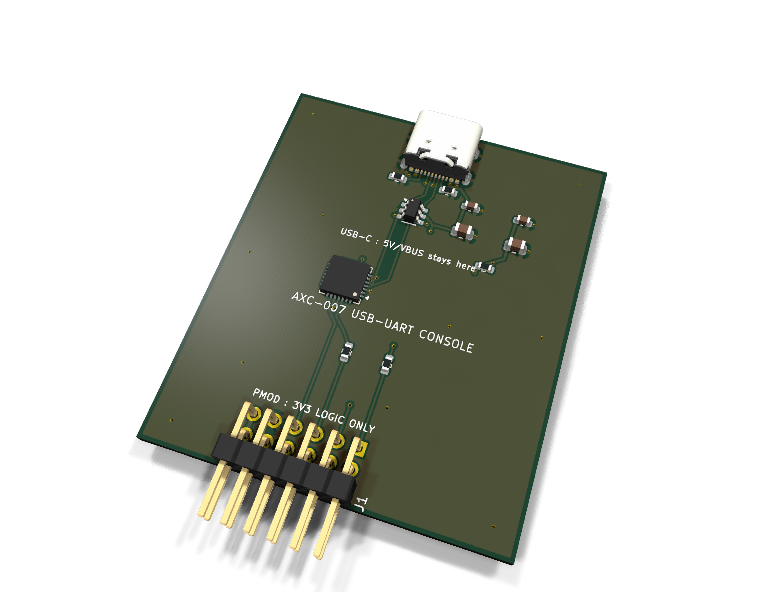
AXC-007 — CP2102N USB-UART console PMOD module
Catalog #7 in the AruviX comms line, level L1 (UART + RTS/CTS). Every AruviOS session needs a console; owning this board makes kits self-contained instead of assuming a random USB dongle. Ships in Phase A with every kit.
Circuit review & bench-test guide →
Components#
Every placed component, with the reason it is on the board. Extracted directly from the schematic, so this cannot drift from the design.
| Ref | Value | What it does on this board | Part number | Footprint |
|---|---|---|---|---|
C1 |
100nF 16V X7R | VREGIN/VBUS HF decoupling | GRM188R71C104KA01DMurata |
C_0603_1608Metric |
C2 |
10uF 10V X5R | VREGIN bulk (>=4.7uF per datasheet) | GRM21BR61A106KE19LMurata |
C_0805_2012Metric |
C3 |
100nF 16V X7R | VDD HF decoupling | GRM188R71C104KA01DMurata |
C_0603_1608Metric |
C4 |
10uF 10V X5R | VDD bulk (>=4.7uF per datasheet) | GRM21BR61A106KE19LMurata |
C_0805_2012Metric |
J1 |
PMOD PLUG 2x6 | PMOD peripheral plug (Digilent spec 1.2) | not selected generic |
PinHeader_2x06_P2.54mm_Horizontal |
J2 |
USB4105-GF-A-120 | USB-C receptacle, USB 2.0, 16 pins (UFP, 5.1k CC pull-downs) | USB4105-GF-A-120GCT Datasheet ↗ |
USB_C_Receptacle_GCT_USB4105-xx-A_16P_TopMnt_Horizontal |
R1 |
5.1k | CC1 pull-down: UFP, advertises default USB power sink | RC0603FR-075K1LYageo Datasheet ↗ |
R_0603_1608Metric |
R2 |
5.1k | CC2 pull-down (both orientations) | RC0603FR-075K1LYageo Datasheet ↗ |
R_0603_1608Metric |
R3 |
10k | ~RST pull-up to CP2102N VDD (belt-and-braces over the internal pull-up) | RC0603FR-0710KLYageo Datasheet ↗ |
R_0603_1608Metric |
R4 |
100R | Series protection on the module-driven data line (CP TXD -> host RXD) | RC0603FR-07100RLYageo Datasheet ↗ |
R_0603_1608Metric |
R5 |
100R | Series protection on the module-driven flow line (CP ~RTS -> host CTS) | RC0603FR-07100RLYageo Datasheet ↗ |
R_0603_1608Metric |
U1 |
CP2102N-A02-GQFN28 | USB 2.0 full-speed to UART bridge, QFN-28 (no VIO pin: I/O at internal VDD 3.3 V) | CP2102N-A02-GQFN28Silicon Labs Datasheet ↗ |
QFN-28-1EP_5x5mm_P0.5mm_EP3.35x3.35mm |
U2 |
USBLC6-2SC6 | USB 2.0 ESD protection array on D+/D- | USBLC6-2SC6STMicroelectronics Datasheet ↗ |
SOT-23-6 |
Signals#
Net labels used in the schematic, which are also the names the HDL top level should use.
3V3 CC1 CC2 CP_RST_N CP_RTS CP_TXD CP_VDD CTS GND RTS RXD TXD USB_DM USB_DP VBUS
Production status#
| Schematic ERC | 0 violations |
|---|---|
| PCB layout | complete |
| DRC | not run |
| Fab package | not exported |
| Fabricated | no — design stage only |
Source: boards/comms-modules/axc-007-console
Catalog #7 in the AruviX comms line (../README.md), level L1 (UART + RTS/CTS). Every AruviOS session needs a console; owning this board makes kits self-contained instead of assuming a random USB dongle. Ships in Phase A with every kit.
Status: schematic generated, ERC clean (0/0), netlist reviewed. PCB layout not started. Not released.
What it teaches#
The kit's first blinky-to-shell moment: UART at up to 3 Mbaud with real RTS/CTS flow control, and (as an L1 board) a clean example of USB-C UFP wiring and bus-powered design.
Design#
- CP2102N-A02-GQFN28 (stock symbol
CP2102N-Axx-xQFN28). - USB-C: exact stock pair proven on
boards/usb-c-5v-breakout—Connector:USB_C_Receptacle_USB2.0_16P+ GCT USB4105 footprint — with 5.1 k CC pull-downs (UFP). USBLC6-2SC6 ESD array on D+/D− (stock, verified). SBU pins open, shield to GND. - Bus-powered per the CP2102N datasheet power-configuration section: VREGIN and the VBUS-sense pin tie to USB VBUS; the internal regulator's 3.3 V comes out on VDD (10 µF + 100 nF on both VREGIN and VDD). Package deviation from the module spec, documented: the QFN28 package has no separate VIO pin (VIO exists only on QFN32) — the datasheet's bus-powered config for this package runs the I/O at VDD = 3.3 V, which satisfies the "VIO must be 3.3 V" requirement by construction.
- Why no 5 V (and no back-feed) reaches the PMOD: VBUS stops at VREGIN/VBUS-sense and the ESD array; the UART pins swing at the internal 3.3 V VDD; and VDD connects to nothing but U1's own decoupling — it is deliberately isolated from the PMOD 3V3 rail, so USB power can never drive the host rail and the host rail never powers U1.
- Direction naming (host FPGA = DTE): CP2102N TXD carries data toward the FPGA → PMOD pin 3 RXD via 100 Ω; FPGA TXD (PMOD pin 2) → CP2102N RXD. Flow control crossed the same way: CP ~RTS → 100 Ω → PMOD pin 1 CTS; FPGA RTS (PMOD pin 4) → CP ~CTS. Module-driven lines carry the 100 Ω.
- ~RST: 10 k pull-up to CP_VDD (over the internal pull-up). Status LEDs on GPIO: skipped for rev 1. Charger-detect (CHREN/CHR0/CHR1) unused.
| PMOD pin | 1 | 2 | 3 | 4 | 5 | 6 | 7–10 | 11 | 12 |
|---|---|---|---|---|---|---|---|---|---|
| Net | CTS | TXD | RXD | RTS | GND | 3V3 | NC | GND | 3V3 |
Regenerate#
python3 generate_design.pyRemaining for release#
- [ ] PCB layout (USB-C at the far edge, matched D± pair), DRC, fab outputs
- [ ] Confirm default CP2102N OTP config (no reprogramming needed for 115200-8N1 enumeration)
- [ ]
hdl/: UART + flow-control loopback demo, AruviOS console bring-up - [ ] BOM export and availability check, design-review checklist